POWER BRAKE UNIT REMOVAL/INSTALLATION [L.H.D. (US)]
POWER BRAKE UNIT REMOVAL/INSTALLATION [L.H.D. (US)]
SM2565968
id041100801855
Replacement Part
|
Gasket
Quantity: 1
Location of use: Power brake unit
|
Brake switch
Quantity: 1
Location of use: Brake pedal
|
Oil and Chemical Type
|
Brake fluid type
Type: SAE J1703 or FMVSS116 DOT-3
|
-
Caution
-
• Once the brake switch clearance has automatically been adjusted, it cannot be adjusted again. Therefore, replace the switch with a new one when replacing the power brake unit or performing any procedure that changes the brake pedal stroke.• Brake fluid will damage painted surfaces. Be careful not to spill any on painted surfaces. In addition, if there is any brake fluid on the wiring harness, the wire insulation may corrode causing a malfunction such as a short circuit. If brake fluid gets on a painted surface or wiring harness, wash and flush it off completely with water immediately.
-
Note
-
• Tighten the brake pipe flare nut using any commercially available flare nut wrench.
1.Disconnect the negative battery terminal. (See NEGATIVE BATTERY TERMINAL DISCONNECTION/CONNECTION [(US)].)
2.Remove the following parts as a single unit. (See INTAKE-AIR SYSTEM REMOVAL/INSTALLATION [SKYACTIV-G (WITH CYLINDER DEACTIVATION (US))].) (See INTAKE-AIR SYSTEM REMOVAL/INSTALLATION [SKYACTIV-G (WITH CYLINDER DEACTIVATION (US))].)
-
• Air hose• Air cleaner cover• Air cleaner element• Air cleaner case• Fresh-air duct• Resonance chamber
3.Remove the battery. (See BATTERY REMOVAL/INSTALLATION [SKYACTIV-G (WITHOUT CYLINDER DEACTIVATION (US))].) (See BATTERY REMOVAL/INSTALLATION [SKYACTIV-G (WITH CYLINDER DEACTIVATION (US))].)
4.Remove the battery tray and PCM component. (See BATTERY REMOVAL/INSTALLATION [SKYACTIV-G (WITHOUT CYLINDER DEACTIVATION (US))].) (See BATTERY REMOVAL/INSTALLATION [SKYACTIV-G (WITH CYLINDER DEACTIVATION (US))].)
5.Set the PCM wiring harness out of the way.
6.Remove the following parts:
- (1)Windshield wiper arm and blade (See WINDSHIELD WIPER ARM AND BLADE REMOVAL/INSTALLATION.)
- (2)Cowl grille (See COWL GRILLE REMOVAL/INSTALLATION.)
- (3)Windshield wiper motor and link (See WINDSHIELD WIPER MOTOR AND LINK REMOVAL/INSTALLATION.)
- (4)Side cowl grille (See COWL GRILLE REMOVAL/INSTALLATION.)
- (5)Cowl panel (See COWL PANEL REMOVAL/INSTALLATION [(US)].)
7.Remove the master cylinder. (See MASTER CYLINDER REMOVAL/INSTALLATION [L.H.D. (US)].)
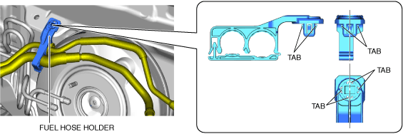
8.Remove the fuel hose holder from the body.
am3zzw00025070
|
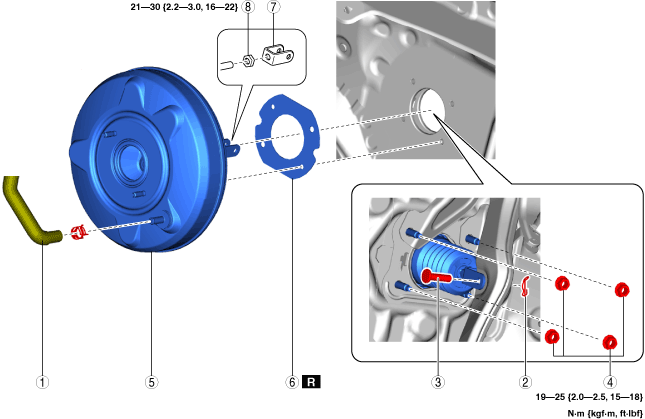
9.Remove in the order indicated in the table.
10.Install in the reverse order of removal.
11.After installation, add brake fluid, bleed the air, and inspect for fluid leakage. (See BRAKE FLUID AIR BLEEDING [(US)].) (See CLUTCH FLUID REPLACEMENT/AIR BLEEDING [C66M-R (US)] (MTX).)
12.Remove the brake switch. (See BRAKE PEDAL REMOVAL/INSTALLATION [L.H.D. (US)].)
13.Inspect the brake pedal. (See BRAKE PEDAL INSPECTION [(US)].)
14.Install a new brake switch. (See BRAKE PEDAL REMOVAL/INSTALLATION [L.H.D. (US)].)
am3zzw00025071
|
|
1
|
Vacuum hose
|
|
2
|
Snap pin
|
|
3
|
Clevis pin
|
|
4
|
Nut
|
|
5
|
Power brake unit
|
|
6
|
Gasket
|
|
7
|
Fork
(See Fork Installation Note.)
|
|
8
|
Locknut
|
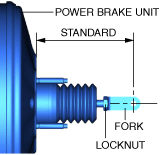
Fork Installation Note
1.Install the fork as shown in the figure.
am3zzw00025072
|
-
Standard
-
• 128.3—129.3 mm {5.052—5.090 in}