BRAKE PEDAL REMOVAL/INSTALLATION [L.H.D. (US)]
BRAKE PEDAL REMOVAL/INSTALLATION [L.H.D. (US)]
SM2565960
id041100801255
Replacement Part
|
Brake switch
Quantity: 1
Location of use: Brake pedal
|
-
Caution
-
• The clearance between the brake switch and the brake pedal is automatically adjusted to the correct amount when the brake switch is inserted into the installation hole on the brake pedal and rotated to fix in place. If the brake switch is not properly installed, the clearance may be incorrect, causing a brake light malfunction. Therefore, always verify that the brake pedal is properly installed and fully released before installing the brake switch to the pedal.• Once the brake switch clearance has automatically been adjusted, it cannot be adjusted again. Therefore, replace the switch with a new one when replacing the power brake unit or the pedal, or performing any procedure that changes the pedal stroke.
1.Disconnect the negative battery terminal. (See NEGATIVE BATTERY TERMINAL DISCONNECTION/CONNECTION [(US)].)
2.Remove the driver-side front heat duct No.1. (See FRONT HEAT DUCT REMOVAL/INSTALLATION [(US)].)
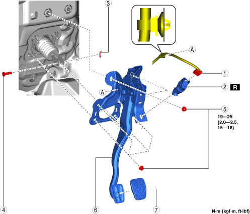
3.Remove in the order indicated in the table.
4.Install in the reverse order of removal.
am3zzw00025051
|
|
1
|
Brake switch connector and wiring harness
|
|
2
|
Brake switch
|
|
3
|
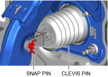
Snap pin
(See Snap Pin Installation Note.)
|
|
4
|
Clevis pin
|
|
5
|
Nut
|
|
6
|
Brake pedal
(See Brake Pedal Removal Note.)
|
|
7
|
Pedal pad
|
Brake Pedal Removal Note
1.Disconnect the connector. (With active driving display)
am3zzw00031478
|
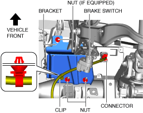
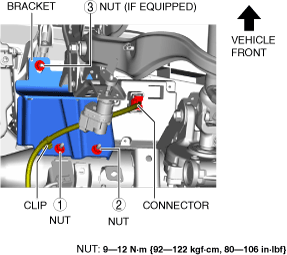
2.Remove the clip. (With active driving display)
3.Remove the nuts. (With bracket)
4.Move the power brake unit to the vehicle front where the power brake unit fork does not interfere with the brake pedal arm.
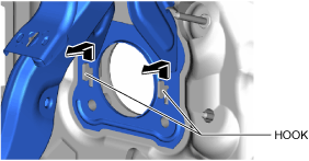
5.Move the brake pedal in the direction of the arrow shown in the figure, and remove it while avoiding the hooks.
am3zzw00025053
|
Brake Pedal Installation Note
1.Temporarily tighten nuts A.
am3zzw00025054
|
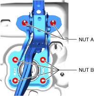
2.Temporarily tighten nuts B.
3.Tighten nuts B to the specified torque.
4.Tighten nuts A to the specified torque.
5.Tighten the nuts in the order shown in the figure. (With bracket)
am3zzw00031281
|
6.Install the clip. (With active driving display)
7.Connect the connector. (With active driving display)
Snap Pin Installation Note
1.Install the snap pin as shown in the figure.
am3zzw00025056
|
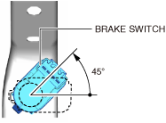
Brake Switch Installation Note
1.Inspect the brake pedal. (See BRAKE PEDAL INSPECTION [(US)].)
2.With the brake pedal fully released, insert the brake switch into the installation hole on the brake pedal.
-
Caution
-
• If the brake pedal arm is moved when securing the brake switch, the clearance between the brake pedal and brake switch may not be adjusted to the correct clearance. Be careful not to move the brake pedal arm when securing the brake switch.
3.Secure the brake switch by turning it counterclockwise 45°.
am3zzw00025057
|