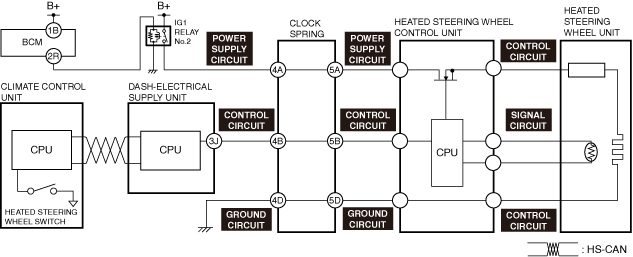
NO.2 HEATED STEERING WHEEL SYSTEM OPERATES CONSTANTLY [HEATED STEERING WHEEL]
NO.2 HEATED STEERING WHEEL SYSTEM OPERATES CONSTANTLY [HEATED STEERING WHEEL]
SM2335530
id0603a3951200
|
Troubleshooting item |
Heated steering wheel system operates constantly |
||
|---|---|---|---|
|
Description
|
Heated steering wheel warms steering wheel even though heated steering wheel switch is off
|
||
|
Possible Causes
|
Heated steering wheel switch is always ON
• Heated steering wheel switch malfunction
Heated steering wheel control unit falsely detects heated steering wheel switch is ON
• Heated steering wheel control unit malfunction
• Clock spring malfunction
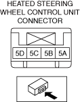
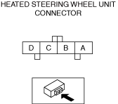
• Open circuit in heated steering wheel control unit control circuit
• Short to ground in heated steering wheel control unit control circuit
• Short to power supply in heated steering wheel control unit control circuit
• Open circuit in clock spring control circuit
• Short to ground in clock spring control circuit
• Short to power supply in clock spring control circuit
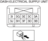
• Dash-electrical supply unit malfunction
• CAN communication line malfunction
|
||
 |
|||
 |
 |
 |
|
 |
 |
 |
|
• When performing an asterisked (*) troubleshooting inspection, shake the wiring harness and connectors while performing the inspection to discover whether poor contact points are the cause of any intermittent malfunctions. If there is a problem, check to make sure connectors, terminals and wiring harnesses are connected correctly and undamaged.
Diagnostic Procedure
|
Step |
Inspection |
Results |
Action |
|---|---|---|---|
|
1
|
DETERMINE IF THE MALFUNCTION CAUSE IS THE HEATED STEERING WHEEL SWITCH
• Switch the ignition off.
• Disconnect the climate control unit connector. (See CLIMATE CONTROL UNIT REMOVAL/INSTALLATION [FULL-AUTO AIR CONDITIONER (US)].) (See CLIMATE CONTROL UNIT REMOVAL/INSTALLATION [MANUAL AIR CONDITIONER (US)].)
• Switch the ignition ON (engine off or on).
• Is the heated steering wheel system operating?
|
Yes
|
Go to the next step.
|
|
No
|
Replace the climate control unit and perform the repair completion verification.
|
||
|
2*
|
INSPECT CLOCK SPRING CONTROL CIRCUIT FOR OPEN CIRCUIT
• Switch the ignition off.
• Disconnect the negative battery terminal and wait for 1 min or more. (See NEGATIVE BATTERY TERMINAL DISCONNECTION/CONNECTION [(US)].)
• Inspect the control circuit for an open circuit. (See CIRCUIT INSPECTION.)
• Is the circuit normal?
|
Yes
|
Go to the next step.
|
|
No
|
Repair or replace the malfunctioning location and perform the repair completion verification.
|
||
|
3*
|
INSPECT CLOCK SPRING CONTROL CIRCUIT FOR SHORT TO GROUND
• Inspect the control circuit for a short to ground. (See CIRCUIT INSPECTION.)
• Is the circuit normal?
|
Yes
|
Go to the next step.
|
|
No
|
Repair or replace the malfunctioning location and perform the repair completion verification.
|
||
|
4*
|
INSPECT CLOCK SPRING CONTROL CIRCUIT FOR SHORT TO POWER SUPPLY
• Inspect the control circuit for a short to power supply. (See CIRCUIT INSPECTION.)
• Is the circuit normal?
|
Yes
|
Go to the next step.
|
|
No
|
Repair or replace the malfunctioning location and perform the repair completion verification.
|
||
|
5*
|
INSPECT HEATED STEERING WHEEL CONTROL UNIT CONTROL CIRCUIT FOR OPEN CIRCUIT
• Inspect the control circuit for an open circuit. (See CIRCUIT INSPECTION.)
• Is the circuit normal?
|
Yes
|
Go to the next step.
|
|
No
|
Repair or replace the malfunctioning location and perform the repair completion verification.
|
||
|
6*
|
INSPECT HEATED STEERING WHEEL CONTROL UNIT CONTROL CIRCUIT FOR SHORT TO GROUND
• Inspect the control circuit for a short to ground. (See CIRCUIT INSPECTION.)
• Is the circuit normal?
|
Yes
|
Go to the next step.
|
|
No
|
Repair or replace the malfunctioning location and perform the repair completion verification.
|
||
|
7*
|
INSPECT HEATED STEERING WHEEL CONTROL UNIT CONTROL CIRCUIT FOR SHORT TO POWER SUPPLY
• Inspect the control circuit for a short to power supply. (See CIRCUIT INSPECTION.)
• Is the circuit normal?
|
Yes
|
Go to the next step.
|
|
No
|
Repair or replace the malfunctioning location and perform the repair completion verification.
|
||
|
8*
|
DETERMINE IF CAUSE OF MALFUNCTION IS CLOCK SPRING
• Inspect for continuity between the following terminals:
• Is there continuity?
|
Yes
|
Refer to the controller area network (CAN) malfunction diagnosis flow to inspect for a CAN communication error.
If the CAN communication is normal, perform the diagnosis from Step 1.
• If the malfunction recurs, replace the climate control unit. (See CLIMATE CONTROL UNIT REMOVAL/INSTALLATION [FULL-AUTO AIR CONDITIONER (US)].) (See CLIMATE CONTROL UNIT REMOVAL/INSTALLATION [MANUAL AIR CONDITIONER (US)].)
|
|
No
|
Replace the clock spring and perform the repair completion verification.
|
||
|
Repair completion verification
|
VERIFY IF MALFUNCTION CAUSE IS CORRECTED
• Always reconnect all disconnected connectors.
• Switch the ignition ON (engine off or on).
• Operate the heated steering wheel switch to turn on the heated steering wheel system.
• Does the heated steering wheel system operate normally?
|
Yes
|
Troubleshooting completed. (Explain the contents of the servicing to the customer.)
|
|
No
|
Verify the malfunction symptom in the symptom troubleshooting chart and perform the other applicable malfunction diagnosis.
|