NO.8 AUTO HOLD DOES NOT WORK [DYNAMIC STABILITY CONTROL (DSC)]
NO.8 AUTO HOLD DOES NOT WORK [DYNAMIC STABILITY CONTROL (DSC)]
SM2335156
id0403b2898900
|
Troubleshooting item |
AUTOHOLD does not work |
|
|---|---|---|
|
Possible cause
|
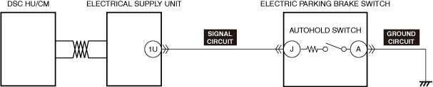
• Stuck AUTOHOLD switch in off position
• Electrical supply unit (ESU) detects a malfunction
• Open circuit in AUTOHOLD switch signal circuit
• Open circuit in AUTOHOLD switch ground circuit
|
|
 |
||
 |
 |
|
Diagnostic procedure
|
Step |
Inspection |
Results |
Action |
|---|---|---|---|
|
1
|
CONFIRM DSC HU/CM DTC
• Retrieve the DSC HU/CM DTC using the M-MDS. (See DTC INSPECTION.)
• Are any DTCs present?
|
Yes
|
Go to the applicable DTC inspection.
(See DTC TABLE [DSC HU/CM (US)].)
|
|
No
|
Go to the next step.
|
||
|
2
|
CONFIRM ELECTRICAL SUPPLY UNIT DTC
• Retrieve the electrical supply unit using the M-MDS. (See DTC INSPECTION.)
• Are any DTCs present?
|
Yes
|
Go to the applicable DTC inspection.
|
|
No
|
Go to the next step.
|
||
|
3
|
INSPECT AUTOHOLD SWITCH
• Inspect the AUTOHOLD switch. (See AUTO HOLD SWITCH INSPECTION.)
• Is the AUTOHOLD switch normal?
|
Yes
|
Go to the next step.
|
|
No
|
Replace the AUTOHOLD switch, and perform the repair completion verification.
|
||
|
4 *
|
INSPECT AUTOHOLD SWITCH GROUND CIRCUIT FOR OPEN CIRCUIT
• Inspect the ground circuit for an open circuit. (See CIRCUIT INSPECTION.)
• Is the circuit normal?
|
Yes
|
Go to the next step.
|
|
No
|
Repair or replace the malfunctioning location, and perform the repair completion verification.
|
||
|
5 *
|
INSPECT AUTOHOLD SWITCH SIGNAL CIRCUIT FOR OPEN CIRCUIT
• Inspect the signal circuit for an open circuit. (See CIRCUIT INSPECTION.)
• Is the circuit normal?
|
Yes
|
Refer to the controller area network (CAN) malfunction diagnosis flow to inspect for a CAN communication error.
If the CAN communication is normal, perform the diagnosis from Step 1.
• If the malfunction recurs, replace the DSC HU/CM. (See DSC HU/CM REMOVAL/INSTALLATION [L.H.D. (US)].)
Perform the repair completion verification.
|
|
No
|
Repair or replace the malfunctioning location, and perform the repair completion verification.
|
||
|
Repair completion verification
|
VERIFY THAT MALFUNCTION SYMPTOMS DO NOT RECUR AFTER REPAIR
• Install/connect the part removed/disconnected during the troubleshooting procedure.
• Has the malfunction symptom been eliminated?
|
Yes
|
Complete the symptom troubleshooting.
Explain to the customer what has been repaired.
|
|
No
|
Refer to the controller area network (CAN) malfunction diagnosis flow to inspect for a CAN communication error.
If the CAN communication is normal, perform the diagnosis from Step 1.
|
• When performing an asterisked (*) troubleshooting inspection, shake the wiring harness and connectors while doing the inspection to discover whether poor contact points are the cause of any intermittent malfunctions. If there is a problem, check to make sure connectors, terminals and wiring harness are connected correctly and undamaged.