NO.1 ANY OF THE FOLLOWING LIGHTS DO NOT ILLUMINATE WITH THE IGNITION ON: (ABS WARNING LIGHT, BRAKE SYSTEM WARNING LIGHT, TCS/DSC INDICATOR LIGHT AND/OR DSC OFF INDICATOR LIGHT) [DYNAMIC STABILITY CONTROL (DSC)]
NO.1 ANY OF THE FOLLOWING LIGHTS DO NOT ILLUMINATE WITH THE IGNITION ON: (ABS WARNING LIGHT, BRAKE SYSTEM WARNING LIGHT, TCS/DSC INDICATOR LIGHT AND/OR DSC OFF INDICATOR LIGHT) [DYNAMIC STABILITY CONTROL (DSC)]
SM2335152
id0403b2890600
|
Troubleshooting item |
Any of the following lights do not illuminate with the ignition ON: (ABS warning light, brake system warning light, TCS/DSC indicator light and/or DSC OFF indicator light) |
|---|---|
|
Possible cause
|
• DSC HU/CM does not operate.
• Communication error between DSC HU/CM and body control module (BCM)
• Communication error between body control module (BCM) and instrument cluster
• Instrument cluster malfunction
• DSC HU/CM internal malfunction
|
 |
|
 |
|
 |
|
Diagnostic procedure
|
Step |
Inspection |
Results |
Action |
|---|---|---|---|
|
1
|
VERIFY WHERE MALFUNCTION IS IN WARNING LIGHTS AND INDICATOR LIGHTS’ COMMON POWER SUPPLY, OR IN OTHER WARNING LIGHTS AND INDICATOR LIGHTS
• Ignition is switched ON (engine off)
• Do other warning and indicator lights illuminate?
|
Yes
|
Go to Step 4.
|
|
No
|
Go to the next step.
|
||
|
*2
|
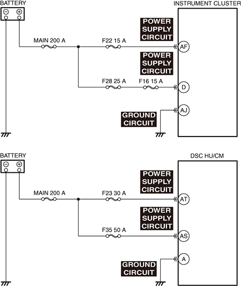
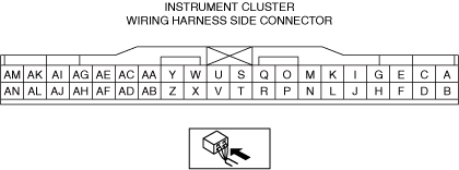
INSPECT INSTRUMENT CLUSTER POWER SUPPLY CIRCUIT FOR SHORT TO GROUND AND OPEN CIRCUIT
• Inspect the power supply circuit for an open circuit and short to ground. (See CIRCUIT INSPECTION.)
• Is the circuit normal?
|
Yes
|
Go to the next step.
|
|
No
|
Repair or replace the malfunctioning location, and perform the repair completion verification.
|
||
|
*3
|
INSPECT INSTRUMENT CLUSTER GROUND CIRCUIT FOR SHORT TO POWER SUPPLY AND OPEN CIRCUIT
• Inspect the ground circuit for an open circuit and short to power supply. (See CIRCUIT INSPECTION.)
• Is the circuit normal?
|
Yes
|
Replace the instrument cluster, and perform the repair completion verification. (Open circuit in the instrument cluster)
|
|
No
|
Repair or replace the malfunctioning location, and perform the repair completion verification.
|
||
|
4
|
CONFIRM DSC HU/CM DTC
• Retrieve the DSC HU/CM DTC using the M-MDS. (See DTC INSPECTION.)
• Are any DTCs present?
|
Yes
|
Go to the applicable DTC inspection.
(See DTC TABLE [DSC HU/CM (US)].)
|
|
No
|
If communication error message is displayed on the M-MDS screen:
• Go to the next step.
If communication error message is not displayed:
• Go to Step 7.
|
||
|
*5
|
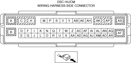
INSPECT DSC HU/CM POWER SUPPLY CIRCUIT FOR SHORT TO GROUND AND OPEN CIRCUIT
• Inspect the power supply circuit for an open circuit and short to ground. (See CIRCUIT INSPECTION.)
• Is the circuit normal?
|
Yes
|
Go to the next step.
|
|
No
|
Repair or replace the malfunctioning location, and perform the repair completion verification.
|
||
|
*6
|
INSPECT DSC HU/CM GROUND CIRCUIT FOR SHORT TO POWER SUPPLY AND OPEN CIRCUIT
• Inspect the power supply circuit for an open circuit and short to power supply. (See CIRCUIT INSPECTION.)
• Is the circuit normal?
|
Yes
|
Replace the DSC HU/CM, and perform the repair completion verification. (Open circuit in the DSC HU/CM)
|
|
No
|
Repair or replace the malfunctioning location, and perform the repair completion verification.
|
||
|
7
|
CONFIRM BODY CONTROL MODULE (BCM) DTC
• Retrieve the body control module (BCM) DTC using the M-MDS. (See DTC INSPECTION.)
• Are any DTCs present?
|
Yes
|
Go to the applicable DTC inspection.
|
|
No
|
Replace the instrument cluster, and perform the repair completion verification.
|
||
|
Repair completion verification
|
VERIFY THAT MALFUNCTION SYMPTOMS DO NOT RECUR AFTER REPAIR
• Install/connect the part removed/disconnected during the troubleshooting procedure.
• Has the malfunction symptom been eliminated?
|
Yes
|
Complete the symptom troubleshooting.
Explain to the customer what has been repaired.
|
|
No
|
Refer to the controller area network (CAN) malfunction diagnosis flow to inspect for a CAN communication error.
If the CAN communication is normal, perform the diagnosis from Step 1.
|
• When performing an asterisked (*) troubleshooting inspection, shake the wiring harness and connectors while doing the inspection to discover whether poor contact points are the cause of any intermittent malfunctions. If there is a problem, check to make sure connectors, terminals and wiring harness are connected correctly and undamaged.