NO.2 ANY OF THE FOLLOWING LIGHTS STAY ON: (ABS WARNING LIGHT, TCS/DSC INDICATOR LIGHT AND/OR DSC OFF INDICATOR LIGHT) [DYNAMIC STABILITY CONTROL (DSC)]
NO.2 ANY OF THE FOLLOWING LIGHTS STAY ON: (ABS WARNING LIGHT, TCS/DSC INDICATOR LIGHT AND/OR DSC OFF INDICATOR LIGHT) [DYNAMIC STABILITY CONTROL (DSC)]
SM2335151
id0403b2890500
|
Troubleshooting item |
Any of the following lights stay on: (ABS warning light, TCS/DSC indicator light and/or DSC OFF indicator light) |
|---|---|
|
Possible cause
|
• No connection at DSC HU/CM connector (When DSC HU/CM connector comes off, ABS warning light, brake system warning light, TCS/DSC indicator light, and DSC OFF indicator light illuminate.)
• DSC HU/CM detected malfunction. (Input and output device malfunction)
• DSC HU/CM detects low voltage in power supply.
• DSC HU/CM ground malfunction (When DSC HU/CM ground is not securely connected, ABS warning light, brake system warning light, TCS/DSC indicator light, and DSC OFF indicator light illuminate but diagnostic trouble code does not display.)
• DSC HU/CM does not operate.
• PCM detected malfunction.
• Body control module (BCM) detected malfunction.
• Error signal input from PCM
• Communication error between DSC HU/CM and instrument cluster
• Communication error between DSC HU/CM and PCM
• Communication error between DSC HU/CM and EPS control module
• Communication error between DSC HU/CM and body control module (BCM)
• Communication error between DSC HU/CM and TCM (ATX)
• Communication error between DSC HU/CM and SAS control module
• After replacing SAS control module low-G sensor and yaw rate sensor initialization have not been performed.
• After replacing DSC HU/CM brake fluid pressure sensor initialization has not been performed.
• Non-completion of module configuration (When module configuration does not carried out, after replacing DSC HU/CM, ABS warning light will stay on.)
• DSC HU/CM internal malfunction
|
 |
|
 |
|
Diagnostic procedure
|
Step |
Inspection |
Results |
Action |
|---|---|---|---|
|
1
|
CONFIRM DSC HU/CM DTC
• Retrieve the DSC HU/CM DTC using the M-MDS. (See DTC INSPECTION.)
• Are any DTCs present?
|
Yes
|
Go to the applicable DTC inspection.
(See DTC TABLE [DSC HU/CM (US)].)
|
|
No
|
If communication error message is displayed on the M-MDS screen:
• Go to the next step.
If communication error message is not displayed:
• Go to Step 5.
|
||
|
2
|
INSPECT CONNECTION OF DSC HU/CM CONNECTOR
• Inspect for connection of the DSC HU/CM connector.
• Is the DSC HU/CM connector connected securely?
|
Yes
|
Go to the next step.
|
|
No
|
Connect the DSC HU/CM connector securely, then go to Step 5.
|
||
|
*3
|
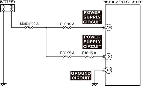
INSPECT DSC HU/CM POWER SUPPLY CIRCUIT FOR SHORT TO GROUND AND OPEN CIRCUIT
• Inspect the power supply circuit for an open circuit and short to ground. (See CIRCUIT INSPECTION.)
• Is the circuit normal?
|
Yes
|
Go to the next step.
|
|
No
|
Repair or replace the malfunctioning location, and perform the repair completion verification.
|
||
|
*4
|
INSPECT DSC HU/CM GROUND CIRCUIT FOR SHORT TO POWER SUPPLY AND OPEN CIRCUIT
• Inspect the ground circuit for an open circuit and short to ground. (See CIRCUIT INSPECTION.)
• Is the circuit normal?
|
Yes
|
Replace the DSC HU/CM, and perform the repair completion verification. (open circuit in the DSC HU/CM)
|
|
No
|
Repair or replace the malfunctioning location, and perform the repair completion verification.
|
||
|
5
|
CONFIRM PCM DTCs
• Retrieve the PCM DTCs using the M-MDS. (See DTC INSPECTION.)
• Are any DTCs present?
|
Yes
|
Go to the applicable DTC inspection.
|
|
No
|
Go to the next step.
|
||
|
6
|
CONFIRM BODY CONTROL MODULE (BCM) DTC
• Retrieve the body control module (BCM) DTC using the M-MDS. (See DTC INSPECTION.)
• Are any DTCs present?
|
Yes
|
Go to the applicable DTC inspection.
|
|
No
|
Go to the next step.
|
||
|
7
|
VERIFY IF MALFUNCTION CAUSED BY INITIALIZATION PROCEDURE FOR MODULE NOT PERFORMED
• Verify if malfunction caused by initialization procedure.
• Has the initial setting been performed after replacing the DSC HU/CM?
|
Yes
|
Replace the instrument cluster, and perform the repair completion verification.
|
|
No
|
Perform the brake fluid pressure sensor initial setting, and perform the repair completion verification.
|
||
|
Repair completion verification
|
VERIFY THAT MALFUNCTION SYMPTOMS DO NOT RECUR AFTER REPAIR
• Install/connect the part removed/disconnected during the troubleshooting procedure.
• Has the malfunction symptom been eliminated?
|
Yes
|
Complete the symptom troubleshooting.
Explain to the customer what has been repaired.
|
|
No
|
Refer to the controller area network (CAN) malfunction diagnosis flow to inspect for a CAN communication error.
If the CAN communication is normal, perform the diagnosis from Step 1.
• If the malfunction recurs, replace the DSC HU/CM. (See DSC HU/CM REMOVAL/INSTALLATION [L.H.D. (US)].)
|
• When performing an asterisked (*) troubleshooting inspection, shake the wiring harness and connectors while doing the inspection to discover whether poor contact points are the cause of any intermittent malfunctions. If there is a problem, check to make sure connectors, terminals and wiring harness are connected correctly and undamaged.