DTC P0117:00 [PCM (SKYACTIV-G)]
DTC P0117:00 [PCM (SKYACTIV-G)]
SM2334508
id0102t4701600
Outline
|
System malfunction location |
ECT sensor No.1 circuit low input |
||||
|---|---|---|---|---|---|
|
Detection condition
|
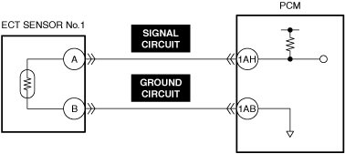
• The PCM monitors the ECT sensor No.1 signal. If the PCM detects that the ECT sensor No.1 voltage at the PCM terminal 1AH is below 0.23 V for 5 s, the PCM determines that the ECT sensor No.1 circuit has a malfunction.
|
||||
|
Fail-safe
|
• Fixes the water temperature for the engine control at 40 °C {104 °F}, and for the idle air control at 80 °C {176 °F}.
• Operates the cooling fan (high speed rotation).
• Inhibits the fuel cut control during shift change.
|
||||
|
Possible cause
|
• Engine overheating (cooling system malfunction)
• ECT sensor No.1 connector or terminals malfunction
• ECT sensor No.1 malfunction
• Short to ground in ECT sensor No.1 signal circuit
• PCM connector or terminals malfunction
• Short circuit in ECT sensor No.1 signal circuit and ground circuit
• PCM malfunction
|
||||
 |
|||||
 |
|||||
 |
|||||
Diagnostic Procedure
|
Step |
Inspection |
Results |
Action |
|---|---|---|---|
|
1
|
RECORD VEHICLE STATUS WHEN DTC WAS DETECTED TO UTILIZE WITH REPEATABILITY VERIFICATION
• Record the freeze frame data/snapshot data.
|
—
|
Go to the next step.
|
|
2
|
VERIFY RELATED REPAIR INFORMATION OR SERVICE INFORMATION AVAILABILITY
• Verify related Service Bulletins, on-line repair information, or Service Information availability.
• Is any related Information available?
|
Yes
|
Perform repair or diagnosis according to the available information.
• If the vehicle is not repaired, go to the next step.
|
|
No
|
Go to the next step.
|
||
|
3
|
VERIFY ENGINE CONDITION
• Verify the engine condition.
• Is the engine overheating?
|
Yes
|
Perform the symptom troubleshooting “COOLING SYSTEM CONCERNS-OVERHEATING”.
|
|
No
|
Go to the next step.
|
||
|
4
|
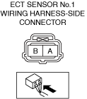
INSPECT ECT SENSOR No.1 CONNECTOR FOR MALFUNCTION
• Inspect the applicable connector and terminal. (See CONNECTOR INSPECTION.)
• Are the connector and terminal normal?
|
Yes
|
Go to the next step.
|
|
No
|
Repair or replace the malfunctioning location and perform the repair completion verification.
|
||
|
5
|
DETERMINE IF ECT SENSOR No.1 OR WIRING HARNESS MALFUNCTION
• Reconnect all disconnected connectors.
• Access the ECT PID using the M-MDS. (See PID/DATA MONITOR INSPECTION.)
• Verify the ECT PID value when disconnecting the ECT sensor No.1 connector.
• Does the ECT PID value change?
|
Yes
|
Replace the ECT sensor No.1 and perform the repair completion verification.
|
|
No
|
Go to the next step.
|
||
|
6
|
INSPECT ECT SENSOR No.1 SIGNAL CIRCUIT FOR SHORT TO GROUND
• Inspect the applicable circuit for a short to ground. (See CIRCUIT INSPECTION.)
• Is the circuit normal?
|
Yes
|
Go to the next step.
|
|
No
|
Repair or replace the malfunctioning location and perform the repair completion verification.
|
||
|
7
|
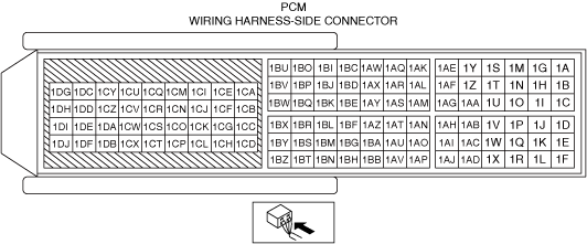
INSPECT PCM CONNECTOR FOR MALFUNCTION
• Inspect the applicable connector and terminal. (See CONNECTOR INSPECTION.)
• Are the connector and terminal normal?
|
Yes
|
Go to the next step.
|
|
No
|
Repair or replace the malfunctioning location and perform the repair completion verification.
|
||
|
8
|
INSPECT ECT SENSOR No.1 SIGNAL CIRCUIT AND GROUND CIRCUIT FOR SHORT CIRCUIT
• Inspect the applicable circuits for a short circuit. (See CIRCUIT INSPECTION.)
• Is the circuit normal?
|
Yes
|
Go to the next step.
|
|
No
|
Repair or replace the malfunctioning location and perform the repair completion verification.
|
||
|
Repair completion verification 1
|
VERIFY THAT VEHICLE IS REPAIRED
• Install/connect the part removed/disconnected during the troubleshooting procedure.
• Clear the DTC recorded in the memory. (See CLEARING DTC.)
• Replicate the vehicle conditions at the time the DTC was detected using the following procedure.
• Perform the DTC inspection for the PCM. (See DTC INSPECTION.)
• Is the same Pending DTC present?
|
Yes
|
Refer to the controller area network (CAN) malfunction diagnosis flow to inspect for a CAN communication error.
If the CAN communication is normal, perform the diagnosis from Step 1.
• If the malfunction recurs, replace the PCM, then go to the next step. (See PCM REMOVAL/INSTALLATION [SKYACTIV-G (WITH CYLINDER DEACTIVATION (US))].) (See PCM REMOVAL/INSTALLATION [SKYACTIV-G (WITHOUT CYLINDER DEACTIVATION (US))].)
|
|
No
|
Go to the next step.
|
||
|
Repair completion verification 2
|
VERIFY IF OTHER DTCs DISPLAYED
• Perform the DTC inspection. (See DTC INSPECTION.)
• Are any other DTCs displayed?
|
Yes
|
Repair the malfunctioning location according to the applicable DTC troubleshooting.
|
|
No
|
DTC troubleshooting completed.
|