DETERMINING SHORT TO POWER SUPPLY LOCATION (CAN-BUS No.7) [(US)]
DETERMINING SHORT TO POWER SUPPLY LOCATION (CAN-BUS No.7) [(US)]
SM2566469
id1002x1004300
-
Caution
-
• Perform the following malfunction diagnosis only when it is diagnosed with a short to ground by CONTROLLER AREA NETWORK (CAN) MALFUNCTION DIAGNOSIS FLOW. (See CONTROLLER AREA NETWORK (CAN) MALFUNCTION DIAGNOSIS FLOW [(US)].)
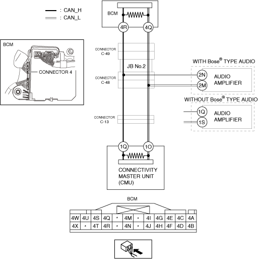
System Wiring Diagram
am3zzw00027518
|
Determination Procedure
-
Caution
-
• When disconnecting the connector, verify that there is no looseness, damage, deformation, corrosion, or poor connection of the connector terminals.• When inspecting the connector, touch it with a paper clip or similar thin pin without directly inserting a tester probe into the terminal.• Disconnect the negative battery cable before performing any work that requires handling of connectors.
|
Step |
Inspection |
Action |
|
|---|---|---|---|
|
1
|
INSPECT CAN LINE BETWEEN CONNECTOR C-49 AND BODY CONTROL MODULE (BCM) FOR SHORT TO POWER SUPPLY
• Switch the ignition off.
• Disconnect the negative battery cable. (See NEGATIVE BATTERY TERMINAL DISCONNECTION/CONNECTION [(US)].)
• Disconnect the connector C-49.
• Connect the negative battery cable. (See NEGATIVE BATTERY TERMINAL DISCONNECTION/CONNECTION [(US)].)
• Switch the ignition ON (engine off).
• Measure the voltage at body control module (BCM) terminals 4R and 4Q.
• Is the voltage between 1.5—3.5 V?
|
Yes
|
Go to Step 3.
|
|
No
|
Go to the next step.
|
||
|
2
|
INSPECT BODY CONTROL MODULE (BCM) FOR SHORT TO POWER SUPPLY
• Switch the ignition off.
• Disconnect the negative battery cable. (See NEGATIVE BATTERY TERMINAL DISCONNECTION/CONNECTION [(US)].)
• Disconnect the connector 4 which has body control module (BCM) terminals 4R and 4Q.
• Connect the connector C-49.
• Connect the negative battery cable. (See NEGATIVE BATTERY TERMINAL DISCONNECTION/CONNECTION [(US)].)
• Switch the ignition ON (engine off).
• Measure the voltage at body control module (BCM) terminals 4R and 4Q (wiring harness side).
• Is the voltage between 1.5—3.5 V?
|
Yes
|
Replace the body control module (BCM) because there is a short to the power supply in the body control module (BCM).
|
|
No
|
Repair or replace the wiring harness between the body control module (BCM) and connector C-49 because the wiring harness is shorted to the power supply.
|
||
|
3
|
INSPECT JB No.2 FOR SHORT TO POWER SUPPLY
• Switch the ignition off.
• Disconnect the negative battery cable. (See NEGATIVE BATTERY TERMINAL DISCONNECTION/CONNECTION [(US)].)
• Connect the connector C-49.
• Disconnect the connector C-48.
• Connect the negative battery cable. (See NEGATIVE BATTERY TERMINAL DISCONNECTION/CONNECTION [(US)].)
• Switch the ignition ON (engine off).
• Measure the voltage at body control module (BCM) terminals 4R and 4Q.
• Is the voltage between 1.5—3.5 V?
|
Yes
|
Go to the next step.
|
|
No
|
Replace the JB No.2 because there is a short to the power supply in the JB No.2.
|
||
|
4
|
INSPECT CAN LINE BETWEEN AUDIO AMPLIFIER AND CONNECTOR C-48 FOR SHORT TO POWER SUPPLY
• Measure the voltage at audio amplifier terminals 2N and 2M. (With Bose ® type audio)
• Measure the voltage at audio amplifier terminals 1Q and 1S. (Without Bose ® type audio)
• Is the voltage between 1.5—3.5 V?
|
Yes
|
Go to Step 6.
|
|
No
|
Go to the next step.
|
||
|
5
|
INSPECT AUDIO AMPLIFIER FOR SHORT TO POWER SUPPLY
• Switch the ignition off.
• Disconnect the negative battery cable. (See NEGATIVE BATTERY TERMINAL DISCONNECTION/CONNECTION [(US)].)
• Disconnect the audio amplifier connector.
• Connect the connector C-48.
• Connect the negative battery cable. (See NEGATIVE BATTERY TERMINAL DISCONNECTION/CONNECTION [(US)].)
• Switch the ignition ON (engine off).
• Measure the voltage at body control module (BCM) terminals 4R and 4Q.
• Is the voltage between 1.5—3.5 V?
|
Yes
|
Replace the audio amplifier because there is a short to the power supply in the audio amplifier.
|
|
No
|
Repair or replace the wiring harness between the audio amplifier and connector C-48 because the wiring harness is shorted to the power supply.
|
||
|
6
|
INSPECT CAN LINE BETWEEN CONNECTOR C-48 AND CONNECTOR C-13 FOR SHORT TO POWER SUPPLY
• Switch the ignition off.
• Disconnect the negative battery cable. (See NEGATIVE BATTERY TERMINAL DISCONNECTION/CONNECTION [(US)].)
• Connect the connector C-48.
• Disconnect the connector C-13.
• Connect the negative battery cable. (See NEGATIVE BATTERY TERMINAL DISCONNECTION/CONNECTION [(US)].)
• Switch the ignition ON (engine off).
• Measure the voltage at body control module (BCM) terminals 4R and 4Q.
• Is the voltage between 1.5—3.5 V?
|
Yes
|
Go to the next step.
|
|
No
|
Repair or replace the wiring harness between the connector C-48 and connector C-13 because the wiring harness is shorted to the power supply.
|
||
|
7
|
INSPECT CONNECTIVITY MASTER UNIT (CMU) FOR SHORT TO POWER SUPPLY
• Switch the ignition off.
• Disconnect the negative battery cable. (See NEGATIVE BATTERY TERMINAL DISCONNECTION/CONNECTION [(US)])
• Disconnect the connectivity master unit (CMU) connector.
• Connect the connector C-13.
• Connect the negative battery cable. (See NEGATIVE BATTERY TERMINAL DISCONNECTION/CONNECTION [(US)])
• Switch the ignition ON (engine off).
• Measure the voltage at body control module (BCM) terminals 4R and 4Q.
• Is the voltage between 1.5—3.5 V?
|
Yes
|
Replace the connectivity master unit (CMU) because there is a short to the power supply in the connectivity master unit (CMU).
|
|
No
|
Repair or replace the wiring harness between the connectivity master unit (CMU) and connector C-13 because the wiring harness is shorted to the power supply.
|
||