DETERMINING SHORT TO POWER SUPPLY LOCATION (CAN-BUS No.4) [(US)]
DETERMINING SHORT TO POWER SUPPLY LOCATION (CAN-BUS No.4) [(US)]
SM2566457
id1002x1003100
-
Caution
-
• Perform the following malfunction diagnosis only when it is diagnosed with a short to ground by CONTROLLER AREA NETWORK (CAN) MALFUNCTION DIAGNOSIS FLOW. (See CONTROLLER AREA NETWORK (CAN) MALFUNCTION DIAGNOSIS FLOW [(US)].)
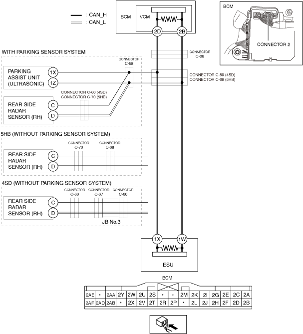
System Wiring Diagram
am3zzw00034236
|
Determination Procedure
-
Caution
-
• When disconnecting the connector, verify that there is no looseness, damage, deformation, corrosion, or poor connection of the connector terminals.• When inspecting the connector, touch it with a paper clip or similar thin pin without directly inserting a tester probe into the terminal.• Disconnect the negative battery cable before performing any work that requires handling of connectors.
|
Step |
Inspection |
Action |
|
|---|---|---|---|
|
1
|
INSPECT CAN LINE BETWEEN BODY CONTROL MODULE (BCM) AND CONNECTOR C-08 FOR SHORT TO POWER SUPPLY
• Switch the ignition off.
• Disconnect the negative battery cable. (See NEGATIVE BATTERY TERMINAL DISCONNECTION/CONNECTION [(US)].)
• Disconnect the connector C-08.
• Connect the negative battery cable. (See NEGATIVE BATTERY TERMINAL DISCONNECTION/CONNECTION [(US)].)
• Switch the ignition ON (engine off).
• Measure the voltage at body control module (BCM) terminals 2D and 2B.
• Is the voltage between 1.5—3.5 V?
|
Yes
|
Go to Step 3.
|
|
No
|
Go to the next step.
|
||
|
2
|
INSPECT BODY CONTROL MODULE (BCM) FOR SHORT TO POWER SUPPLY
• Switch the ignition off.
• Disconnect the negative battery cable. (See NEGATIVE BATTERY TERMINAL DISCONNECTION/CONNECTION [(US)].)
• Disconnect the connector 2 which has body control module (BCM) terminals 2D and 2B.
• Connect the connector C-08.
• Connect the negative battery cable. (See NEGATIVE BATTERY TERMINAL DISCONNECTION/CONNECTION [(US)].)
• Switch the ignition ON (engine off).
• Measure the voltage at body control module (BCM) terminals 2D and 2B (wiring harness side).
• Is the voltage between 1.5—3.5 V?
|
Yes
|
Replace the body control module (BCM) because there is a short to the power supply in the body control module (BCM).
|
|
No
|
Repair or replace the wiring harness between the body control module (BCM) and connector C-08 because the wiring harness is shorted to the power supply.
|
||
|
3
|
INSPECT CAN LINE BETWEEN CONNECTOR C-08 AND CONNECTOR C-59/C-69 FOR SHORT TO POWER SUPPLY
• Switch the ignition off.
• Disconnect the negative battery cable. (See NEGATIVE BATTERY TERMINAL DISCONNECTION/CONNECTION [(US)].)
• Connect the connector C-08.
• Disconnect the connector C-59.(4SD)
• Disconnect the connector C-69.(5HB)
• Connect the negative battery cable. (See NEGATIVE BATTERY TERMINAL DISCONNECTION/CONNECTION [(US)].)
• Switch the ignition ON (engine off).
• Measure the voltage at body control module (BCM) terminals 2D and 2B.
• Is the voltage between 1.5—3.5 V?
|
Yes
|
Go to the next step.
|
|
No
|
Repair or replace the wiring harness between connector C-08 and connector C-59/C-69 because the wiring harness is shorted to the power supply.
|
||
|
4
|
INSPECT CAN LINE BETWEEN CONNECTOR C-59/C-69 AND ELECTRICAL SUPPLY UNIT (ESU) FOR SHORT TO POWER SUPPLY
• Measure the voltage at electrical supply unit (ESU) terminals 1X and 1W.
• Is the voltage between 1.5—3.5 V?
|
Yes
|
Go to Step 6. (with parking sensor system)
Go to Step 11. (5HB (without parking sensor system))
Go to Step 14. (4SD (without parking sensor system))
|
|
No
|
Go to the next step.
|
||
|
5
|
INSPECT PARKING ASSIST UNIT (ULTRASONIC) FOR SHORT TO POWER SUPPLY
• Switch the ignition off.
• Disconnect the negative battery cable. (See NEGATIVE BATTERY TERMINAL DISCONNECTION/CONNECTION [(US)].)
• Connect the connector C-58.
• Disconnect the parking assist unit (ultrasonic) connector.
• Connect the negative battery cable. (See NEGATIVE BATTERY TERMINAL DISCONNECTION/CONNECTION [(US)].)
• Switch the ignition ON (engine off).
• Measure the voltage at body control module (BCM) terminals 2D and 2B.
• Is the voltage between 1.5—3.5 V?
|
Yes
|
Replace the electrical supply unit (ESU) because there is a short to the power supply in the electrical supply unit (ESU).
|
|
No
|
Repair or replace the wiring harness between the electrical supply unit (ESU) and connector C-59/C-69 because the wiring harness is shorted to the power supply.
|
||
|
6
|
INSPECT CAN LINE BETWEEN CONNECTOR C-58 AND CONNECTOR C-59/C-69 FOR SHORT TO POWER SUPPLY
• Switch the ignition off.
• Disconnect the negative battery cable. (See NEGATIVE BATTERY TERMINAL DISCONNECTION/CONNECTION [(US)].)
• Connect the connector C-59.(4SD)
• Connect the connector C-69.(5HB)
• Disconnect the connector C-58.
• Connect the negative battery cable. (See NEGATIVE BATTERY TERMINAL DISCONNECTION/CONNECTION [(US)].)
• Switch the ignition ON (engine off).
• Measure the voltage at body control module (BCM) terminals 2D and 2B.
• Is the voltage between 1.5—3.5 V?
|
Yes
|
Go to the next step.
|
|
No
|
Repair or replace the wiring harness between connector C-58 and connector C-59/C-69 because the wiring harness is shorted to the power supply.
|
||
|
7
|
INSPECT CAN LINE BETWEEN PARKING ASSIST UNIT (ULTRASONIC) AND CONNECTOR C-58 FOR SHORT TO POWER SUPPLY
• Measure the voltage at parking assist unit (ultrasonic) terminals 1X and 1Z.
• Is the voltage between 1.5—3.5 V?
|
Yes
|
Go to Step 9.
|
|
No
|
Go to the next step.
|
||
|
8
|
INSPECT PARKING ASSIST UNIT (ULTRASONIC) FOR SHORT TO POWER SUPPLY
• Switch the ignition off.
• Disconnect the negative battery cable. (See NEGATIVE BATTERY TERMINAL DISCONNECTION/CONNECTION [(US)].)
• Connect the connector C-58.
• Disconnect the parking assist unit (ultrasonic) connector.
• Connect the negative battery cable. (See NEGATIVE BATTERY TERMINAL DISCONNECTION/CONNECTION [(US)].)
• Switch the ignition ON (engine off).
• Measure the voltage at body control module (BCM) terminals 2D and 2B.
• Is the voltage between 1.5—3.5 V?
|
Yes
|
Replace the parking assist unit (ultrasonic) because there is a short to the power supply in the parking assist unit (ultrasonic).
|
|
No
|
Repair or replace the wiring harness between the parking assist unit (ultrasonic) and connector C-58 because the wiring harness is shorted to the power supply.
|
||
|
9
|
INSPECT CAN LINE BETWEEN REAR SIDE RADAR SENSOR (RH) AND CONNECTOR C-60/C-70 FOR SHORT TO POWER SUPPLY
• Switch the ignition off.
• Disconnect the negative battery cable. (See NEGATIVE BATTERY TERMINAL DISCONNECTION/CONNECTION [(US)].)
• Connect the connector C-58.
• Disconnect the connector C-60.(4SD)
• Disconnect the connector C-70.(5HB)
• Connect the negative battery cable. (See NEGATIVE BATTERY TERMINAL DISCONNECTION/CONNECTION [(US)].)
• Switch the ignition ON (engine off).
• Measure the voltage at body control module (BCM) terminals 2D and 2B.
• Is the voltage between 1.5—3.5 V?
|
Yes
|
Go to the next step.
|
|
No
|
Repair or replace the wiring harness between connector C-60/C-70 and connector C-58 because the wiring harness is shorted to the power supply.
|
||
|
10
|
INSPECT REAR SIDE RADAR SENSOR (RH) FOR SHORT TO POWER SUPPLY
• Switch the ignition off.
• Disconnect the negative battery cable. (See NEGATIVE BATTERY TERMINAL DISCONNECTION/CONNECTION [(US)].)
• Connect the connector C-60.
• Disconnect the rear side radar sensor (RH) connector.
• Connect the negative battery cable. (See NEGATIVE BATTERY TERMINAL DISCONNECTION/CONNECTION [(US)].)
• Switch the ignition ON (engine off).
• Measure the voltage at body control module (BCM) terminals 2D and 2B.
• Is the voltage between 1.5—3.5 V?
|
Yes
|
Replace the rear side radar sensor (RH) because there is a short to the power supply in the rear side radar sensor (RH).
|
|
No
|
Repair or replace the wiring harness between the rear side radar sensor (RH) and connector C-60/C-70 because the wiring harness is shorted to the power supply.
|
||
|
11
|
INSPECT CAN LINE BETWEEN CONNECTOR C-68 AND CONNECTOR C-69 FOR SHORT TO POWER SUPPLY
• Switch the ignition off.
• Disconnect the negative battery cable. (See NEGATIVE BATTERY TERMINAL DISCONNECTION/CONNECTION [(US)].)
• Connect the connector C-69.
• Disconnect the connector C-68.
• Connect the negative battery cable. (See NEGATIVE BATTERY TERMINAL DISCONNECTION/CONNECTION [(US)].)
• Switch the ignition ON (engine off).
• Measure the voltage at body control module (BCM) terminals 2D and 2B.
• Is the voltage between 1.5—3.5 V?
|
Yes
|
Go to the next step.
|
|
No
|
Repair or replace the wiring harness between the connector C-68 and connector C-69 because the wiring harness is shorted to the power supply.
|
||
|
12
|
INSPECT CAN LINE BETWEEN CONNECTOR C-70 AND CONNECTOR C-68 FOR SHORT TO POWER SUPPLY
• Switch the ignition off.
• Disconnect the negative battery cable. (See NEGATIVE BATTERY TERMINAL DISCONNECTION/CONNECTION [(US)].)
• Disconnect the connector C-70.
• Connect the connector C-68
• Connect the negative battery cable. (See NEGATIVE BATTERY TERMINAL DISCONNECTION/CONNECTION [(US)].)
• Switch the ignition ON (engine off).
• Measure the voltage at body control module (BCM) terminals 2D and 2B.
• Is the voltage between 1.5—3.5 V?
|
Yes
|
Go to the next step.
|
|
No
|
Repair or replace the wiring harness between the connector C-70 and connector C-68 because the wiring harness is shorted to the power supply.
|
||
|
13
|
INSPECT REAR SIDE RADAR SENSOR (RH) FOR SHORT TO POWER SUPPLY
• Switch the ignition off.
• Disconnect the negative battery cable. (See NEGATIVE BATTERY TERMINAL DISCONNECTION/CONNECTION [(US)].)
• Connect the connector C-70.
• Disconnect the rear side radar sensor (RH) connector.
• Connect the negative battery cable. (See NEGATIVE BATTERY TERMINAL DISCONNECTION/CONNECTION [(US)].)
• Switch the ignition ON (engine off).
• Measure the voltage at body control module (BCM) terminals 2D and 2B.
• Is the voltage between 1.5—3.5 V?
|
Yes
|
Replace the rear side radar sensor (RH) because there is a short to the power supply in the rear side radar sensor (RH).
|
|
No
|
Repair or replace the wiring harness between the rear side radar sensor (RH) and connector C-70 because the wiring harness is shorted to the power supply.
|
||
|
14
|
INSPECT CAN LINE BETWEEN CONNECTOR C-66 AND CONNECTOR C-59 FOR SHORT TO POWER SUPPLY
• Switch the ignition off.
• Disconnect the negative battery cable. (See NEGATIVE BATTERY TERMINAL DISCONNECTION/CONNECTION [(US)].)
• Connect the connector C-59.
• Disconnect the connector C-66.
• Connect the negative battery cable. (See NEGATIVE BATTERY TERMINAL DISCONNECTION/CONNECTION [(US)].)
• Switch the ignition ON (engine off).
• Measure the voltage at body control module (BCM) terminals 2D and 2B.
• Is the voltage between 1.5—3.5 V?
|
Yes
|
Go to the next step.
|
|
No
|
Repair or replace the wiring harness between the connector C-66 and connector C-59 because the wiring harness is shorted to the power supply.
|
||
|
15
|
INSPECT JB No.3 FOR SHORT TO POWER SUPPLY
• Switch the ignition off.
• Disconnect the negative battery cable. (See NEGATIVE BATTERY TERMINAL DISCONNECTION/CONNECTION [(US)].)
• Connect the connector C-66.
• Disconnect the connector C-67.
• Connect the negative battery cable. (See NEGATIVE BATTERY TERMINAL DISCONNECTION/CONNECTION [(US)].)
• Switch the ignition ON (engine off).
• Measure the voltage at body control module (BCM) terminals 2D and 2B.
• Is the voltage between 1.5—3.5 V?
|
Yes
|
Go to the next step.
|
|
No
|
Replace the JB No.3 because there is a short to the power supply in the JB No.3.
|
||
|
16
|
INSPECT CAN LINE BETWEEN CONNECTOR C-60 AND CONNECTOR C-67 FOR SHORT TO POWER SUPPLY
• Switch the ignition off.
• Disconnect the negative battery cable. (See NEGATIVE BATTERY TERMINAL DISCONNECTION/CONNECTION [(US)].)
• Disconnect the connector C-60.
• Connect the connector C-67
• Connect the negative battery cable. (See NEGATIVE BATTERY TERMINAL DISCONNECTION/CONNECTION [(US)].)
• Switch the ignition ON (engine off).
• Measure the voltage at body control module (BCM) terminals 2D and 2B.
• Is the voltage between 1.5—3.5 V?
|
Yes
|
Go to the next step.
|
|
No
|
Repair or replace the wiring harness between the connector C-60 and connector C-67 because the wiring harness is shorted to the power supply.
|
||
|
17
|
INSPECT REAR SIDE RADAR SENSOR (RH) FOR SHORT TO POWER SUPPLY
• Switch the ignition off.
• Disconnect the negative battery cable. (See NEGATIVE BATTERY TERMINAL DISCONNECTION/CONNECTION [(US)].)
• Connect the connector C-60.
• Disconnect the rear side radar sensor (RH) connector.
• Connect the negative battery cable. (See NEGATIVE BATTERY TERMINAL DISCONNECTION/CONNECTION [(US)].)
• Switch the ignition ON (engine off).
• Measure the voltage at body control module (BCM) terminals 2D and 2B.
• Is the voltage between 1.5—3.5 V?
|
Yes
|
Replace the rear side radar sensor (RH) because there is a short to the power supply in the rear side radar sensor (RH).
|
|
No
|
Repair or replace the wiring harness between the rear side radar sensor (RH) and connector C-60 because the wiring harness is shorted to the power supply.
|
||