POWER BRAKE UNIT INSPECTION [(US)]
POWER BRAKE UNIT INSPECTION [(US)]
SM2565967
id041100801798
Special Service Tool (SST)
|
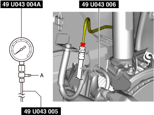
49 U043 004A
Oil pressure gauge
(Part of 49 U043 0A0A)
|
 |
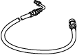
49 U043 005
Joint
(Part of 49 U043 0A0A)
|
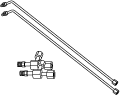 |
49 U043 006
Hose
(Part of 49 U043 0A0A)
|
 |
|
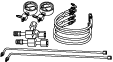
49 U043 0A0A
Oil pressure gauge set
|
 |
—
|
—
|
||
Oil and Chemical Type
|
Brake fluid type
Type: SAE J1703 or FMVSS116 DOT-3
|
-
Caution
-
• Brake fluid will damage painted surfaces. Be careful not to spill any on painted surfaces. In addition, if there is any brake fluid on the wiring harness, the wire insulation may corrode causing a malfunction such as a short circuit. If brake fluid gets on a painted surface or wiring harness, wash and flush it off completely with water immediately.
-
Note
-
• The following inspection methods are simple inspection methods to determine the function of the power brake unit.• If there is any malfunction in the power brake unit, replace the power brake unit as a single unit. (See POWER BRAKE UNIT REMOVAL/INSTALLATION [L.H.D. (US)].)• Tighten the brake pipe flare nut using any commercially available flare nut wrench.
Without Using SST
Operation inspection
1.With the engine stopped, pump the brake pedal a few times.
2.With the brake pedal depressed, start the engine.
3.If the brake pedal moves down slightly immediately after starting the engine, the unit is normal.
Vacuum function inspection
1.Start the engine.
2.Stop the engine after driving the vehicle for 1—2 min.
3.Depress the brake pedal with normal force.
4.If the first pedal stroke is long and becomes shorter with subsequent strokes, the unit is normal.
-
• If a problem is found, inspect for damage to or improper installation of the check valve and vacuum hose. After repairing, inspect again.
Vacuum loss function inspection
1.Start the engine.
2.Depress the brake pedal with normal force.
3.With the brake pedal is depressed, stop the engine.
4.Hold the brake pedal depressed for approx. 30 s.
5.If the brake pedal height does not change during this time, the unit is normal.
Using SST
-
Note
-
• When performing the inspection using the SST, inspect the brake pipe on the left or right front wheel.• The following procedure and figures show the inspection for the brake pipe on the left front wheel.
Pre-inspection preparation
1.Remove the wheel and tire. (See WHEEL AND TIRE REMOVAL/INSTALLATION.)
2.Disconnect the brake pipe from the brake hose.
am3zzw00025068
|
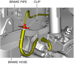
3.Remove the clip.
4.Remove the brake hose from the bracket.
5.Install the SSTs to the brake pipe as shown in the figure.
am3zzw00025069
|
6.Bleed the brake line and the SSTs of air. Bleed the air form the SSTs using bleeder screw A.
7.Install the pedal force gauge to the brake pedal.
8.Connect the vacuum gauge to the vacuum line.
Vacuum loss inspection
1.Start the engine.
2.Depress the brake pedal with a force of 200 N {20.4 kgf, 45.0 lbf}.
3.Stop the engine when the vacuum gauge reading reaches 68 kPa {510 mmHg, 20 inHg} with the brake pedal depressed.
4.With the engine off, observe the vacuum gauge for 15 s.
5.If the gauge has dropped 3.3 kPa {25 mmHg, 0.97 inHg} or less, the unit is normal.
Lack of hydraulic pressure inspection
1.If the brake pedal force and fluid pressure correlation is within the specification with the engine stopped and a vacuum amount of 0 kPa {0 mmHg, 0 inHg}, the system is normal.
Master cylinder fluid pressure
|
Vacuum amount at 0 kPa {0 mmHg, 0 inHg} |
|
|---|---|
|
Brake pedal force |
Fluid pressure |
|
200 N {20.4 kgf, 45.0 lbt}
|
610 kPa {6.22 kgf/cm 2, 88.5 psi} or more
|
Hydraulic pressure inspection
1.Start the engine. Depress the brake pedal when the vacuum reaches 66.7 kPa {500 mmHg, 19.7 inHg}.
2.At this time, apply the indicated brake pedal force and if the fluid pressure is within the specification, the unit is normal.
Master cylinder fluid pressure
|
Vacuum amount at 66.7 kPa {500 mmHg, 19.7 inHg} |
|
|---|---|
|
Brake pedal force |
Fluid pressure |
|
200 N {20.4 kgf, 45.0 lbt}
|
8,550 kPa {87.18 kgf/cm 2, 1,240 psi} or more
|
After-inspection procedure
1.After the inspection, remove the SSTs, install the brake hose, clip, and brake pipe to the original positions, and then bleed the air from the brake line. (See FRONT BRAKE HOSE REMOVAL/INSTALLATION [(US)].) (See BRAKE FLUID AIR BLEEDING [(US)].)