ENGINE MOUNT DISASSEMBLY/ASSEMBLY [SKYACTIV-G (WITHOUT CYLINDER DEACTIVATION (US))]
ENGINE MOUNT DISASSEMBLY/ASSEMBLY [SKYACTIV-G (WITHOUT CYLINDER DEACTIVATION (US))]
SM2565616
id0110u0806900
No.1 Engine Mount
1.Remove the front under cover No.2. (See FRONT UNDER COVER No.2 REMOVAL/INSTALLATION.)
2.Remove in the order indicated in the table.
3.Install in the reverse order of removal.
am3zzw00034663
|
|
1
|
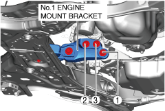
No.1 engine mount bracket
(See No.3 Engine Mount.)
|
|
2
|
No.1 engine mount rubber
(See No.3 Engine Mount.)
|
1.Tighten the No.1 engine mount bracket installation bolts in the order shown in the figure.
am3zzw00024947
|
2.Temporarily tighten the No.1 engine mount rubber installation bolts in the order shown in the figure.
am3zzw00024948
|
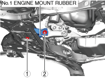
3.Tighten the No.1 engine mount rubber installation bolts in the order shown in the figure.
am3zzw00024948
|
No.3 Engine Mount
-
Caution
-
• Slots have been adopted for the No.3 engine mount installation holes. If the No.3 engine mount is deviated from the original position when installing the No.3 engine mount, engine noise or vibration could increase. Before removing the No.3 engine mount, place alignment marks on the No.3 engine mount and body so that they can be assembled to the same positions as before removal.
1.Disconnect the negative battery terminal. (See NEGATIVE BATTERY TERMINAL DISCONNECTION/CONNECTION [(US)].)
2.Remove the plug hole plate. (See PLUG HOLE PLATE REMOVAL/INSTALLATION [SKYACTIV-G (WITH CYLINDER DEACTIVATION (US))].)
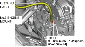
3.Remove the bolt shown in the figure and set the ground cable aside.
am3zzw00024949
|
4.Set the cooler hose (LO) aside. (See REFRIGERANT LINE REMOVAL/INSTALLATION [SKYACTIV-G 2.0, SKYACTIV-G 2.5].)
5.Set the coolant reserve tank aside.
6.Remove the front under cover No.2. (See FRONT UNDER COVER No.2 REMOVAL/INSTALLATION.)
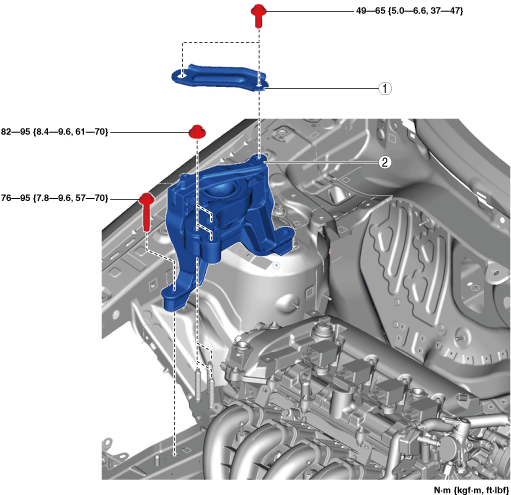
7.Remove in the order indicated in the table.
8.Install in the reverse order of removal.
am3zzw00024950
|
|
1
|
No.3 engine mount bracket
|
|
2
|
No.3 engine mount
|
No.3 engine mount removal note
-
Caution
-
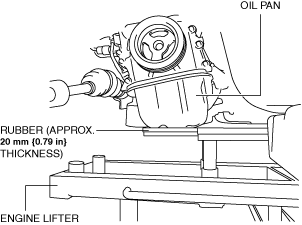
• To prevent deformation of the oil pan, support the engine using the following methods.
-
― When using an engine lifter, insert rubber of appropriate size (approx. 20 mm {0.79 in} thickness) between the engine lifter and the oil pan to support the oil pan.― When using a garage jack, place rubber of appropriate size (approx. 20 mm {0.79 in} thickness) on a batten which is large enough to cover the oil pan to support the oil pan.
-
1.Before removing the No.3 engine mount, support the engine (oil pan) using a commercially available engine lifter or garage jack.
ac5uuw00006935
|
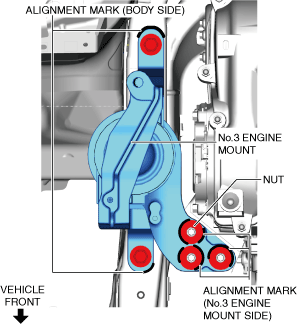
2.Place alignment marks on the locations shown in the figure so that they can be assembled to the same positions as before removal.
am3zzw00024951
|
-
Note
-
• Paint so that the No.3 engine mount is framed on the body side and the outline of the nut is framed on the No.3 engine mount side.
3.Remove the No.3 engine mount.
No.3 engine mount installation note
-
Note
-
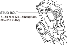
• When replacing the No.3 engine mount, place a mark at the same position as the one placed before removal.• If the No.3 engine mount nut is loosened, tighten the engine front cover stud bolts because they may have loosened.
1.Tighten the engine front cover stud bolts.
am3zzw00031763
|
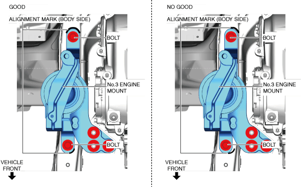
2.Temporarily tighten the No.3 engine mount installation bolts and nuts using the following procedure:
- (1)Align the alignment marks on the body side and No.3 engine mount, and temporarily tighten the bolts shown in the figure.
-
 am3zzw00024952
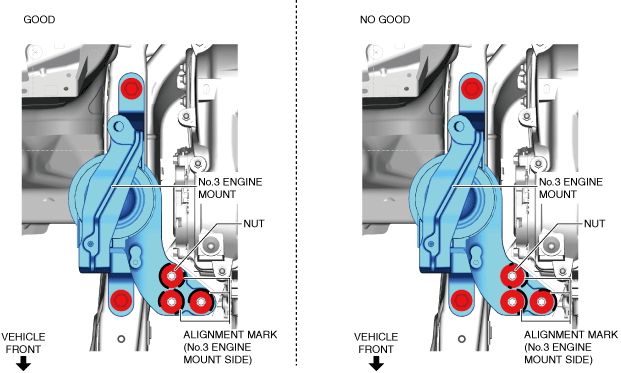
- (2)Temporarily tighten the nuts shown in the figure while aligning the alignment marks of the No.3 engine mount and nuts.
-
-
• If the alignment marks are not aligned, align the alignment marks while slightly moving the engine and temporarily tighten the nuts.
am3zzw00024953 -
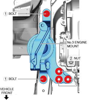
3.Tighten the No.3 engine mount installation bolts and nuts in the order shown in the figure.
am3zzw00024954
|
4.Remove the engine lifter or garage jack.
5.Install in the reverse order of removal.
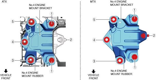
No.4 Engine Mount
-
Caution
-
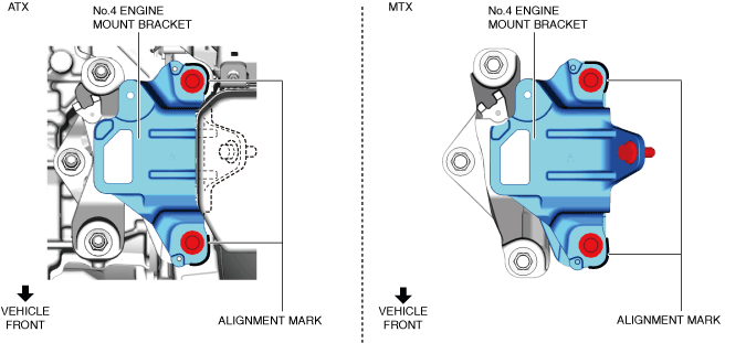
• Slots have been adopted for the No.4 engine mount bracket installation holes. If the No.4 engine mount bracket is deviated from the original position when installing the No.4 engine mount bracket, engine noise or vibration could increase. Before removing the No.4 engine mount bracket, place alignment marks on the No.4 engine mount bracket so that they can be assembled to the same positions as before removal.
1.Disconnect the negative battery terminal. (See NEGATIVE BATTERY TERMINAL DISCONNECTION/CONNECTION [(US)].)
2.Remove the following parts as a single unit: (See INTAKE-AIR SYSTEM REMOVAL/INSTALLATION [SKYACTIV-G (WITH CYLINDER DEACTIVATION (US))].)
-
• Air hose• Air cleaner cover• Air cleaner element• Air cleaner case• Fresh-air duct• Resonance chamber
3.Remove the PCM component. (See PCM REMOVAL/INSTALLATION [SKYACTIV-G (WITH CYLINDER DEACTIVATION (US))].)
4.Remove the battery and battery tray. (See BATTERY REMOVAL/INSTALLATION [SKYACTIV-G (WITHOUT CYLINDER DEACTIVATION (US))].)
5.Disconnect the control cable. (MTX) (See CONTROL CABLE REMOVAL/INSTALLATION [C66M-R (US)].)
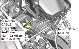
6.Remove the bolt shown in the figure and set the ground cable aside.
am3zzw00032942
|
7.Remove the front under cover No.2. (See FRONT UNDER COVER No.2 REMOVAL/INSTALLATION.)
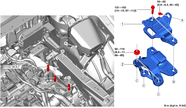
8.Remove in the order indicated in the table.
9.Install in the reverse order of removal.
am3zzw00032943
|
|
1
|
No.4 engine mount bracket
|
|
2
|
No.4 engine mount rubber
|
No.4 engine mount bracket removal note
-
Caution
-
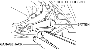
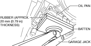
• To prevent damage to the transaxle, support the transaxle using the following methods.
-
― MTX: Support the clutch housing using a batten of appropriate size.am3zzw00024957
-
― ATX: Place rubber of appropriate size (approx. 20 mm {0.79 in} thickness) on a batten which is large enough to cover and support the oil pan.am3zzw00024958
-
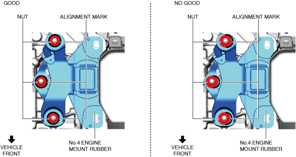
1.Place alignment marks on the locations shown in the figure so that they can be assembled to the same positions as before removal.
am3zzw00024959
|
-
Note
-
• Paint so that the outline of the nut is framed on the bracket side.
2.Before removing the No.4 engine mount bracket, support the transaxle using a commercially available engine lifter or garage jack.
3.Remove the No.4 engine mount bracket.
No.4 engine mount rubber removal note
1.Before removing the No.4 engine mount rubber, support the transaxle using a commercially available engine lifter or garage jack.
2.Remove the No.4 engine mount rubber.
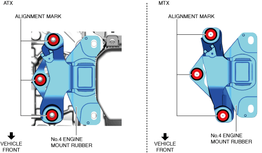
3.Place alignment marks on the locations shown in the figure so that they can be assembled to the same positions as before removal.
am3zzw00024960
|
-
Note
-
• Paint so that the outline of the nut is framed on the bracket side.
No.4 engine mount bracket and rubber installation note
-
Note
-
• When replacing the No.4 engine mount bracket, place a mark at the same position as the one placed before removal.• If the No.4 engine mount bracket nut is loosened, tighten the transaxle stud bolts because they may have loosened.
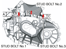
1.Measure the projection of the transaxle stud bolts. (MTX)
-
• If the projection amount is not within the range, adjust the projection amount of the stud bolt.am6xuw00011730
-
Projection A of stud bolt No.1
-
40.0—42.0 mm {1.58—1.65 in}
-
Projection B of stud bolt No.2
-
30.7—32.7 mm {1.21—1.28 in}
-
Projection C of stud bolt No.3
-
70.7—72.7 mm {2.79—2.86 in}
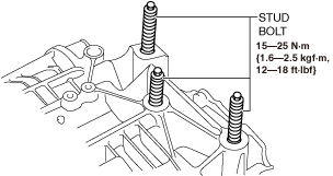
2.Tighten the transaxle stud bolts. (ATX)
am3zzw00031764
|
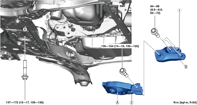
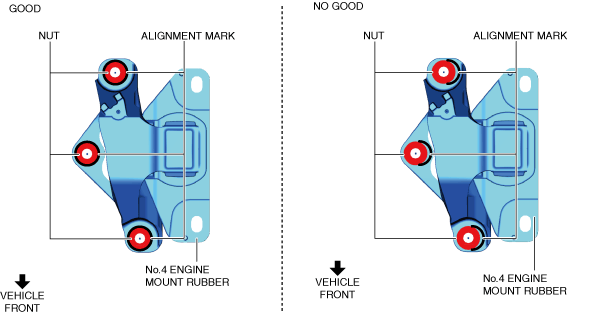
3.Align the alignment marks on the No.4 engine mount rubber and nuts, and temporarily tighten the nuts shown in the figure.
ATX
am3zzw00024961
|
MTX
am3zzw00024962
|
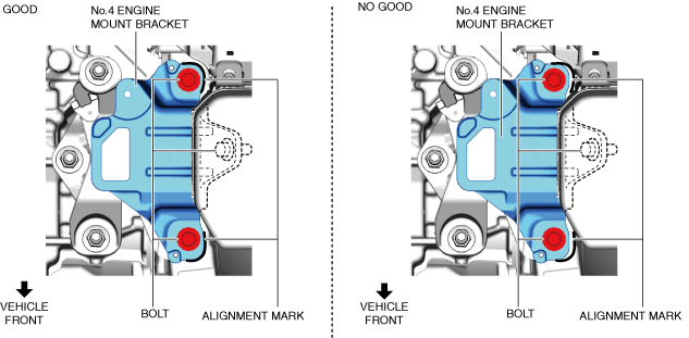
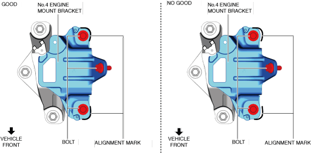
4.Align the alignment marks on the No.4 engine mount bracket and bolts, and temporarily tighten the bolts shown in the figure.
ATX
am3zzw00024963
|
MTX
am3zzw00024964
|
5.Install the No.4 engine mount bracket and rubber and temporarily tighten the nuts and bolts shown in the figure.
am3zzw00024965
|