BASIC KNOWLEDGE
BASIC KNOWLEDGE
SM2337313
id990200000100
Outline
Terminology
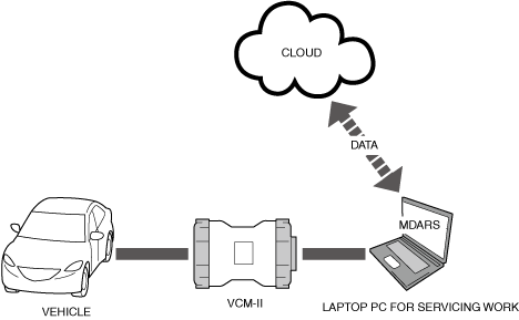
Mazda Modular Diagnostic System (M-MDS)
-
• The M-MDS is an on-board diagnostic tool developed for the improvement of servicing efficiency, maintenance quality, and convenience, and the reduction of security risk.• The M-MDS consists of a laptop PC for servicing work, the Mazda Diagnostic and Repair Software (MDARS) on-board diagnostic software, the VCM- used as a communication device between the vehicle and the laptop PC for servicing work, and each type of cable.
 am3zzw00024591• With the MDARS, cloud technology is introduced for the storage of diagnosis history performed using applications (software for controlling on-board diagnosis function) or the MDARS, and data recorded by the PID/data monitor function.
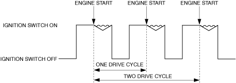
Drive cycle
-
• A drive cycle indicates the period of time in which the engine is started to when it is started the next time.• One drive cycle indicates one period of time in which the engine is started to when it is started the next time. If this cycle is repeated two times, it becomes two drive cycles.atsvuw00000065
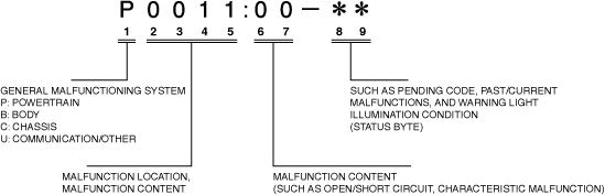
Diagnostic Trouble Code(s) (DTC)
-
• DTC is a code consisting of 9-digit alphanumeric characters which are stored when each module detects a malfunction.• The first 5 digits of the DTC indicate which system or part and what kind of malfunction is occurring. Digits 6 to 7 add more detailed information on the malfunction content (such as open/short circuit, characteristic malfunction).• The last 2 digits of the DTC are called status byte indicating malfunction conditions such as pending code, past/current malfunctions, and the warning light illumination condition.am3zzw00031576
-
Current malfunction
-
― Malfunction being detected by current drive cycle
-
Past malfunction
-
― Malfunction detected by past drive cycle, but with current drive cycle, status is determined as normal
• DTCs can be read out by implementing a quick check or an on-demand self-test using the M-MDS. (See DTC INSPECTION.)• Status byte can be read out by implementing a quick check using the M-MDS. (See DTC INSPECTION.)• For details on the status byte, verify the explanation displayed on the M-MDS screen when reading out DTCs. -
Pending code
-
• The pending code is a temporary malfunction code which differs from the DTC stored when the PCM or TCM detects a system malfunction.• When the PCM or TCM detects a system malfunction, a DTC is stored in the PCM or TCM according to the number of drive cycles. On the other hand, the pending code is stored in the PCM or TCM regardless of the number of drive cycles.• When the PCM or TCM determines that the system is normal, the pending code stored in the PCM or TCM is cleared from the PCM or TCM from the next drive cycle.• Pending codes can be read out by implementing a quick check or an on-demand self-test using the M-MDS. (See DTC INSPECTION.)
Continuous Memory Diagnostic Trouble Code (CMDTC)
-
• CMDTC are the currently stored DTCs which are recorded in a module after clearing the previous DTCs, regardless of past/current malfunctions.• CMDTC can be read out by implementing a quick check using the M-MDS. (See DTC INSPECTION.)
On Demand Diagnostic Trouble Code (ODDTC)
-
• ODDTC are DTCs which have been read out by implementing the diagnostic procedure programmed in the module beforehand.• ODDTC can be read out by implementing an on-demand self-test using the M-MDS. (See DTC INSPECTION.)
Data logger
-
• The data logger is data in which the voltage values input by each module from parts such as switches and actuators is converted to signals for use in on-board diagnostics.• The data logger can be used to implement the PID/data monitor function which reads input/output signals, and the simulation function which drives output parts. (See PID/data monitor function.) (See Simulation function.)
Freeze frame data, Snapshot data
-
• The freeze frame data and snapshot data consist of vehicle condition data when a malfunction is detected.• The freeze frame data and snapshot data are displayed automatically when displaying CMDTC.
-
Freeze frame data
-
• For the freeze frame data, only a part of the DTC data is stored.• If there are several malfunctions in the engine control system, the data for the malfunction which occurred initially is stored. After that, if a misfire or malfunction in the fuel injection control occurs, the misfire or malfunction data in the fuel injection control overwrites the previously stored data. However, if the previously stored freeze frame data is due to a misfire or malfunction in the fuel injection control, the data is not overwritten.
-
Snapshot data
-
• For the snapshot data, the data for all DTCs currently detected is stored.• For DTCs with one drive cycle, the data is stored when a malfunction is determined.• For DTCs with two drive cycles, the data is stored when a malfunction is not determined (first diagnosis) and a malfunction is determined (second diagnosis).
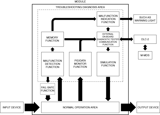
Functions
-
― Malfunction detection function― External on-board diagnostic tester communication function― Memory function― Malfunction indication function― PID/data monitor function― Simulation function― Self-test function― OBD test mode
Malfunction detection function
-
• The malfunction detection function is a function which detects malfunctions by monitoring the operation status of each system from input/output signals.
External on-board diagnostic tester communication function
-
• The external on-board diagnostic tester communication function is for sending/receiving data to and from each module and the external on-board diagnostic tester mutually.• The M-MDS has been adopted as an external on-board diagnostic tester, and DLC-2 has been adopted as a communication media.
-
Data Link Connector (DLC) -2
-
• A DLC-2 compliant with the International Standardization Organization (ISO) standard has been adopted.• Connector shapes and terminal layouts as specified by ISO 15031-3 (SAE J1962) have been adopted, and the terminals are 16-pin.am3zzw00024593
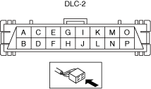
—: Not applicable
|
Terminal |
Function |
|---|---|
|
A
|
Terminal for battery power supply
|
|
B
|
Terminal for headlight auto leveling system initial setting
|
|
C
|
SAS control module
|
|
D
|
—
|
|
E
|
Terminal LO for HS-CAN
|
|
F
|
Terminal HI for HS-CAN
|
|
G
|
—
|
|
H
|
Ground terminal for serial communication
|
|
I
|
—
|
|
J
|
Body ground terminal
|
|
K
|
—
|
|
L
|
—
|
|
M
|
—
|
|
N
|
—
|
|
O
|
—
|
|
P
|
—
|
Memory function
-
• The memory function stores malfunctions detected by the malfunction detection function in the volatile memory or non-volatile memory in each module as a DTC.• The stored DTC can be read by the M-MDS. (See DTC INSPECTION.)• The DTCs stored in the non-volatile memory are not cleared even if the ignition is switched off or the negative battery terminal is disconnected. Therefore, it is necessary to clear the memory from each module after repairing the malfunctions. (See CLEARING DTC.)
Malfunction indication function
-
• The malfunction indication function turns on/flashes the warning lights in the instrument cluster when a malfunction is detected and displays warnings on the center display and the multi-information display to notify the driver of a malfunction.• If a malfunction occurs in the engine control system, the check engine light turns on.• When the PCM determines that a system is continuously normal for 3 drive cycles, it turns off the check engine light, and when it determines that the system is continuously normal for 41 warm-up cycles, it clears the DTC.
-
Note
-
• A warm-up cycle is a drive cycle including the period until the engine is completely warmed up after a cold-engine starts. This cycle repeated 41 times is a 41 warm-up cycle.
-
PID/data monitor function
-
• The PID/data monitor function can select the input/output signal monitor items set in each module and read out in real-time.• The PID/data monitor function can be used by the M-MDS. (See PID/DATA MONITOR INSPECTION.)
Simulation function
-
• The simulation function can drive the output parts set in each module regardless of the control condition.• The simulation function can be used by the M-MDS. (See SIMULATION INSPECTION.)
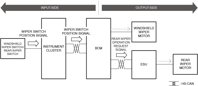
How to make use of PID/data monitor function and simulation function (Ex. Wipers do not operate correctly)
-
• A system (such as input/output side) where a malfunction is occurring can be specified by using the PID/data monitor function or simulation function.am3zzw00024594
-
Input system examination (windshield wiper switch to body control module (BCM))
-
1. Operate the windshield wiper switch and verify that the windshield wiper operation condition is in conjunction with the body control module (BCM) PID “F_WIP” (windshield wiper operation condition table) value.
—: Not applicable
|
Windshield wiper switch condition |
PID/data monitor item “F_WIP” value |
Diagnostic result |
Malfunctioning system |
Inspection item |
|---|---|---|---|---|
|
OFF
|
OFF
|
Normal
|
—
|
—
|
|
LO
|
OFF
|
Malfunction
|
Input system (Windshield wiper switch—Body control module (BCM))
|
• Windshield wiper switch
• Instrument cluster
• Body control module (BCM)
• Related connectors
• Related wiring harness
|
|
HI
|
FrontWiper On Hi
|
Normal
|
—
|
—
|
|
INT/AUTO
|
FrontWiperINT Auto On
|
Normal
|
—
|
—
|
-
Output system examination (body control module (BCM) to wiper motor)
-
1. Verify that the wipers are operating correctly using the body control module (BCM) simulation PID item “F_WIP_REQ” (windshield wiper drive) and “R_WIP_REQ” (rear wiper drive).
—: Not applicable
|
Simulation item “F_WIP_REQ” value |
Simulation item “R_WIP_REQ” value |
Windshield wiper operation condition |
Rear wiper operation condition |
Diagnostic result |
Malfunctioning system |
Inspection item |
|---|---|---|---|---|---|---|
|
Off
|
—
|
OFF
|
—
|
Normal
|
—
|
—
|
|
F.WiperLo
|
—
|
LO
|
—
|
Normal
|
—
|
—
|
|
F.WiperHi
|
—
|
HI
|
—
|
Normal
|
—
|
—
|
|
—
|
Off
|
—
|
OFF
|
Normal
|
—
|
—
|
|
—
|
Rear Wiper Low On
|
—
|
OFF
|
Malfunction
|
Output system (Body control module (BCM)—Rear wiper motor)
|
• Body control module (BCM)
• Electrical supply unit (ESU)
• Rear wiper motor
• Related connectors
• Related wiring harness
|
Self-test function
-
• If the self-test function is performed, each module diagnoses the system. If a malfunction is detected, the applicable DTC is stored.• Current malfunction verification and verification after repair can be facilitated by performing the self-test function.
-
Quick check
-
• When the quick check is implemented, the CMDTCs recorded in all the modules can be read out at once regardless of past/current malfunctions. (See DTC INSPECTION.)
-
On-demand self-test
-
• When the on-demand self test is implemented, the current malfunctions of the selected module can be read out. (See DTC INSPECTION.)• There are two types of the ODDTC self-tests; KOEO (key ON, ignition off) self-test while the ignition is switched ON and engine is stopped, and KOER (key ON, ignition running) self-test while idling and the vehicle is stopped.• The DTCs which can be read out by the on-demand self test are not stored in the module, but with the M-MDS, the CMDTCs are read out automatically after the ODDTCs read out, and both of the results are displayed.
On-Board Diagnostic (OBD) test mode
-
• The OBD system detects malfunction in the exhaust gas purification system and evaporative gas leakage of the vehicle itself, and it records that malfunction content.• Diagnosis related to the OBD system can be facilitated using the OBD test mode.
-
Mode 1: On-Board system readiness test
-
• In Mode 1, the completion status of the PID/data monitor related to the exhaust gas purification system and related system monitors can be verified.• The system monitor verifies whether the operation condition such as for misfire, fuel, CCM, catalyst, evaporative gas, HO2S, and HO2S heater is operating normally.
-
Mode 2: Freeze frame data
-
• Mode 2 reads out the freeze frame data.• The M-MDS displays the freeze frame data automatically when the CMDTCs are displayed.
-
Mode 3: Exhaust gas purification system related CMDTC
-
• Mode 3 reads out the CMDTCs related to the exhaust gas purification system.• When a quick check is performed, the M-MDS automatically reads out the CMDTCs related to the exhaust gas purification system.
-
Mode 4: Exhaust gas purification system-related malfunction information deletion/reset
-
• Mode 4 deletes/resets information (such as CMDTC, pending code, and freeze frame data) related to the exhaust gas purification system.• When the DTCs are cleared, the M-MDS automatically deletes/resets the information related to the exhaust gas purification system.
-
Mode 5: HO2S monitor test
-
• Mode 5 reads out the results of HO2S monitor test.• The M-MDS does not support because it substitutes for Mode 6.
-
Mode 6: Diagnostic monitoring test
-
• Mode 6 reads out the results (number of misfires of each cylinder) of each system monitor test.
-
Mode 7: Pending code
-
• Mode 7 reads out the pending codes.• When a self-test is performed, the M-MDS automatically reads out the pending codes.
-
Mode 8: Force drive
-
• Mode 8 performs force drive.• The M-MDS is used only for forcibly driving the valve for the outlet opening to atmosphere of the charcoal canister to check for fuel evaporative gas leakage.
-
Mode 9: Vehicle information read out
-
• Mode 9 reads out information such as the vehicle identification number and calibration ID number.
Topological figure
am3zzw00034894
|
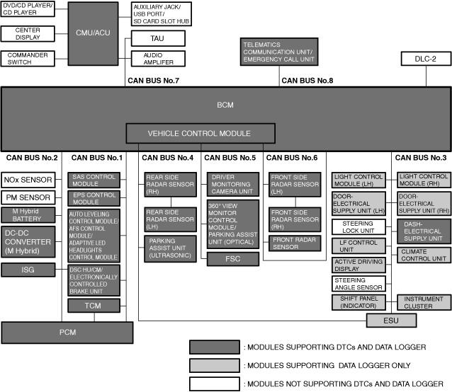
Parent/child module diagnosis
-
• Each CAN bus consists of a parent module which integrates multiple modules, and other child modules.• When a child module detects a malfunction, it sends the malfunction information to the parent module via CAN communication, and the parent module outputs a DTC according to the malfunction content.
-
Note
-
• DTCs are not supported, but because the data logger also has child modules which it supports, verify DTCs even with the child modules if the PID/data monitor function or simulation function is used.
• The parent/child module relationship for each CAN bus is as follows. -
—: Not applicable
|
Parent module |
Body control module (BCM) |
Vehicle control module |
PCM |
TCM |
|---|---|---|---|---|
|
Child module
|
Electrical supply unit (ESU)
|
Rear side radar sensor
|
NOx sensor
|
Shift panel (indicator)
|
|
Door-electrical supply unit
|
Front radar sensor
|
PM sensor
|
—
|
|
|
LF control unit
|
Parking assist unit (ultrasonic)
|
—
|
—
|
|
|
Light control module
|
Driver monitoring camera unit
|
—
|
—
|
|
|
Instrument cluster
|
360° view monitor control module
|
—
|
—
|
|
|
Active driving display
|
Parking assist unit (optical)
|
—
|
—
|
|
|
Steering angle sensor
|
Forward sensing camera (FSC)
|
—
|
—
|
|
|
—
|
Front side radar sensor
|
—
|
—
|
Block Diagram
am3zzw00024595
|