ANTENNA FEEDER NO.1 REMOVAL/INSTALLATION [(US)]
ANTENNA FEEDER NO.1 REMOVAL/INSTALLATION [(US)]
SM2336669
id0920008122x1
4SD
1.Position the front seat back to the fully reclined position and slide the front seat to its furthest rearward position.
2.Disconnect the negative battery terminal. (See NEGATIVE BATTERY TERMINAL DISCONNECTION/CONNECTION [(US)].)
3.Remove the following parts:
- (1)Front map light (See FRONT MAP LIGHT REMOVAL/INSTALLATION [(US)].)
- (2)Sunvisor (See SUNVISOR REMOVAL/INSTALLATION.)
- (3)Assist handle (See ASSIST HANDLE REMOVAL/INSTALLATION.)
- (4)A-pillar trim (See A-PILLAR TRIM REMOVAL/INSTALLATION.)
- (5)Front seat belt lower anchor (See FRONT SEAT BELT REMOVAL/INSTALLATION.)
- (6)B-pillar upper trim (See B-PILLAR UPPER TRIM REMOVAL/INSTALLATION.)
- (7)C-pillar trim (See C-PILLAR TRIM REMOVAL/INSTALLATION.)
- (8)Shift lever knob (MTX) (See SHIFT LEVER REMOVAL/INSTALLATION [C66M-R].)
- (9)Selector lever knob (ATX) (See SELECTOR LEVER COMPONENT REMOVAL/INSTALLATION.)
- (10)Shift panel (See SHIFT PANEL REMOVAL/INSTALLATION.)
- (11)Front console box (See FRONT CONSOLE BOX REMOVAL/INSTALLATION.)
- (12)Cup holder (See CUP HOLDER REMOVAL/INSTALLATION.)
- (13)Side wall (See SIDE WALL REMOVAL/INSTALLATION.)
- (14)Rear console (See REAR CONSOLE REMOVAL/INSTALLATION [(US)].)
- (15)Rear console bracket No.1 (See REAR CONSOLE REMOVAL/INSTALLATION [(US)].)
- (16)Headliner (See HEADLINER REMOVAL/INSTALLATION [(US)].)
- (17)Rear seat cushion (See REAR SEAT CUSHION REMOVAL/INSTALLATION.)
- (18)Rear seat back (See REAR SEAT BACK REMOVAL/INSTALLATION.)
- (19)Tire house trim (See TIRE HOUSE TRIM REMOVAL/INSTALLATION.)
- (20)Rear package trim (See REAR PACKAGE TRIM REMOVAL/INSTALLATION.)
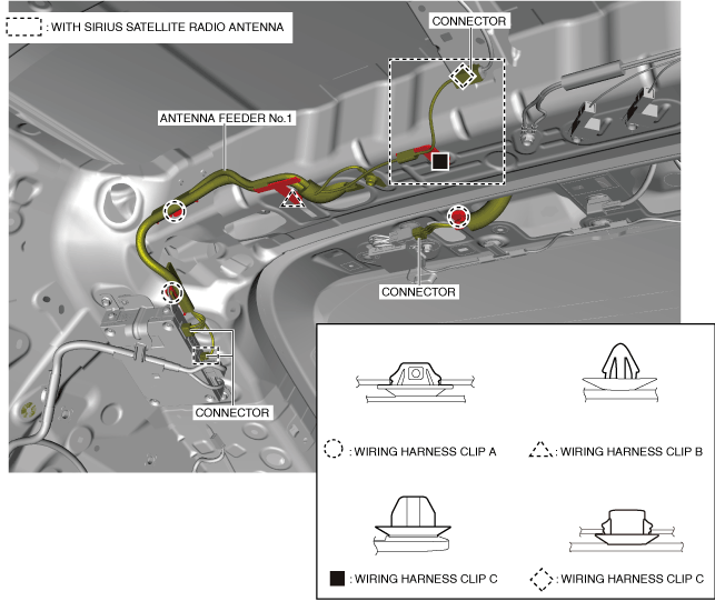
4.Disconnect the connectors and remove wiring harness clips A, B and C.
am3zzw00031829
|
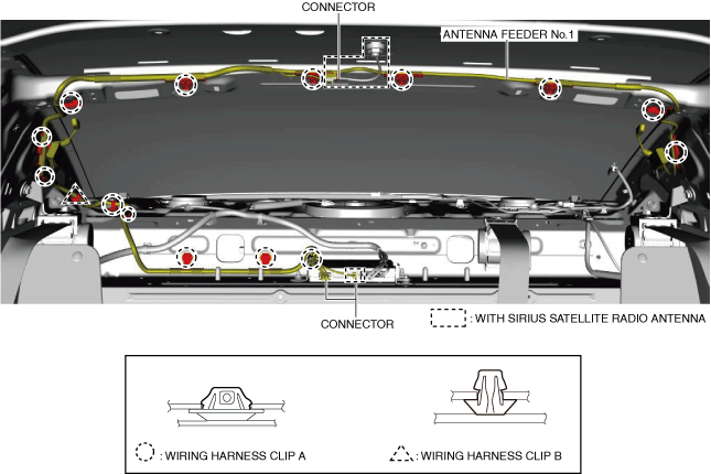
5.Remove the glass antenna terminal cover in the direction of the arrow shown in the figure.
am3zzw00021983
|
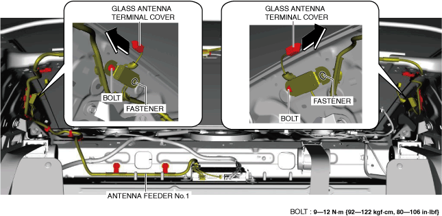
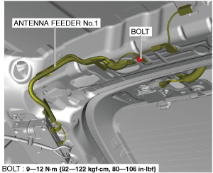
6.Remove the bolts.
7.Remove the fasteners.
8.Remove the antenna feeder No.1.
9.Install in the reverse order of removal.
5HB
Replacement part
|
Inner liftgate grommet
Quantity: 2
Location of use: Liftgate
|
1.Disconnect the negative battery terminal. (See NEGATIVE BATTERY TERMINAL DISCONNECTION/CONNECTION [(US)].)
2.Remove the following parts:
- (1)Front map light (See FRONT MAP LIGHT REMOVAL/INSTALLATION [(US)].)
- (2)Sunvisor (See SUNVISOR REMOVAL/INSTALLATION.)
- (3)Assist handle (See ASSIST HANDLE REMOVAL/INSTALLATION.)
- (4)A-pillar trim (See A-PILLAR TRIM REMOVAL/INSTALLATION.)
- (5)Front seat belt lower anchor (See FRONT SEAT BELT REMOVAL/INSTALLATION.)
- (6)B-pillar upper trim (See B-PILLAR UPPER TRIM REMOVAL/INSTALLATION.)
- (7)Rear package tray (See REAR PACKAGE TRAY REMOVAL/INSTALLATION.)
- (8)Trunk side upper trim (See TRUNK SIDE UPPER TRIM REMOVAL/INSTALLATION.)
- (9)C-pillar trim (See C-PILLAR TRIM REMOVAL/INSTALLATION.)
- (10)Liftgate upper trim (See LIFTGATE UPPER TRIM REMOVAL/INSTALLATION.)
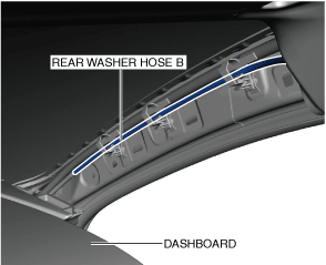
3.Disconnect rear washer hose B.
am3zzw00021984
|
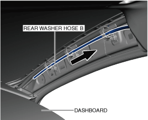
4.Pull the rear washer hose B in the direction of the arrow shown in the figure.
am3zzw00021985
|
5.Disconnect rear washer hose B from the joint pipe.
am3zzw00024139
|

6.Disconnect rear washer hose C from the joint pipe.
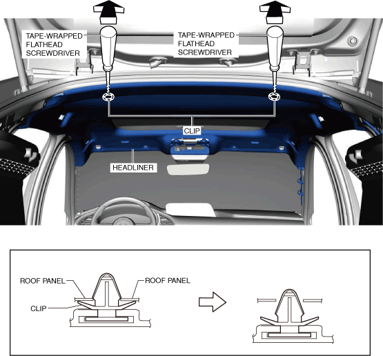
7.Move the headliner in the direction of the arrow shown in the figure and detach the surface fasteners from the sunroof unit. (with sunroof system)
am3zzw00029309
|

8.Insert a tape-wrapped flathead screwdriver into the position shown in the figure, move it in the direction of the arrow, and detach the clips.
am3zzw00021988
|
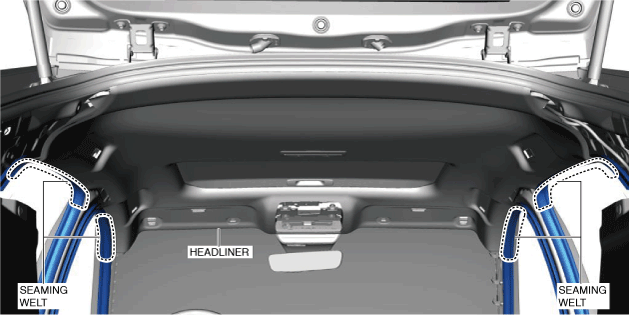
9.Partially peel back the seaming welts.
am3zzw00021989
|
10.Move the headliner in the direction of the arrow shown in the figure and set it on front seats and rear seats.
am3zzw00021990
|

11.Remove the bolt.
am3zzw00021991
|
12.Disconnect the connectors and remove wiring harness clips A, B, C and D.
am3zzw00031670
|
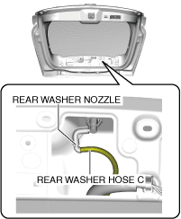
13.Disconnect rear washer hose C from the rear washer nozzle.
am3zzw00024142
|
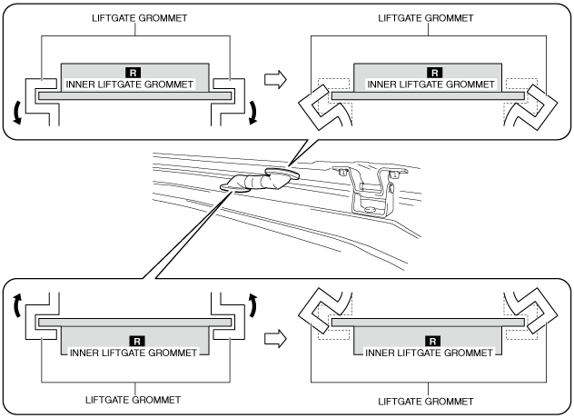
14.Partially peel the liftgate grommets in the direction of the arrows shown in the figures, and remove the liftgate grommets from the inner liftgate grommets.
am3zzw00021993
|
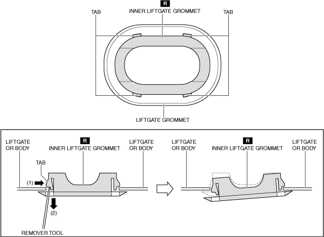
15.While pressing the inner liftgate grommet tab in the order of arrows (1) and (2) using the remover tool, remove each inner liftgate grommet from the liftgate and the body. (See Liftgate Grommet Installation Note.)
am3zzw00021994
|
16.Remove the antenna feeder No.1.
17.Install in the reverse order of removal.
Liftgate Grommet Installation Note
1.Install the liftgate grommet using the following procedure.
- (1)Engage a new inner liftgate grommet as shown in the figure.
-
-
Caution
-
• If the inner liftgate grommet is removed once the attaching ability of the tabs weaken and it may cause leakage. Always replace it with a new one if it is removed once.
 am3uuw00015836
-

- (2)Install the inner liftgate grommet to the liftgate grommet.
-
-
Caution
-
• Install the inner liftgate grommet so that there is no gap between the liftgate grommet and the inner liftgate grommet. Otherwise, it may cause water leakage.am3zzw00021995
-

- (3)Move the inner liftgate grommet in the direction of the arrow shown in the figure and engage the tabs of the inner liftgate grommet on the liftgate side.
-
-
Caution
-
• After installing the liftgate grommet, shake the inner liftgate grommet to verify that the tabs are securely engaged.
am3zzw00021996 -
