POWER SEAT SYSTEM DOES NOT OPERATE [POWER SEAT SYSTEM]
POWER SEAT SYSTEM DOES NOT OPERATE [POWER SEAT SYSTEM]
SM2336306
id0903p4022600
Outline
|
Description
|
• The power seat does not operate even though the power seat switch is operated.
|
|
|
Possible cause
|
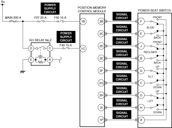
• Connector or terminal malfunction of the following parts:
• Short or open circuit to ground in the following wiring harnesses
• Power seat switch malfunction
• Position memory control module malfunction
|
|
 |
||
 |
 |
|
 |
||
Diagnostic Procedure
|
Step |
Inspection |
Results |
Action |
|---|---|---|---|
|
1
|
VERIFY ALL SYSTEM DTCs
• Perform the DTC inspection. (See DTC INSPECTION.)
• Are any DTCs displayed?
|
Yes
|
Repair the malfunctioning location according to the applicable DTC troubleshooting.
|
|
No
|
Go to the next step.
|
||
|
2
|
INSPECT POSITION MEMORY CONTROL MODULE AND POWER SEAT SWITCH CONNECTORS FOR MALFUNCTION
• Inspect the applicable connector and terminal. (See CONNECTOR INSPECTION.)
• Are the connector and terminal normal?
|
Yes
|
Go to the next step.
|
|
No
|
Repair or replace the malfunctioning location and perform the repair completion verification.
|
||
|
3
|
INSPECT POSITION MEMORY CONTROL MODULE POWER SUPPLY CIRCUIT FOR SHORT TO GROUND AND OPEN CIRCUIT
• Inspect the power supply circuit for a short to ground and open circuit. (See CIRCUIT INSPECTION.)
• Is the circuit normal?
|
Yes
|
Go to the next step.
|
|
No
|
Repair or replace the malfunctioning location and perform the repair completion verification.
|
||
|
4
|
INSPECT POWER SEAT SWITCH SIGNAL CIRCUIT FOR SHORT TO GROUND AND OPEN CIRCUIT
• Inspect the signal circuit for a short to ground and open circuit. (See CIRCUIT INSPECTION.)
• Is the circuit normal?
|
Yes
|
Go to the next step.
|
|
No
|
Repair or replace the malfunctioning location and perform the repair completion verification.
|
||
|
5
|
INSPECT POWER SEAT SWITCH FOR MALFUNCTION
• Inspect the applicable part. (See POWER SEAT SWITCH INSPECTION.)
• Is the part normal?
|
Yes
|
Go to the next step.
|
|
No
|
Repair or replace the malfunctioning location and perform the repair completion verification.
|
||
|
Repair completion verification
|
VERIFY THAT VEHICLE IS REPAIRED
• Install/connect the part removed/disconnected during the troubleshooting procedure.
• Has the malfunction symptom been eliminated?
|
Yes
|
Complete the symptom troubleshooting. (Explain contents of repair to customer)
|
|
No
|
Refer to the controller area network (CAN) malfunction diagnosis flow to inspect for a CAN communication error.
If the CAN communication is normal, perform the diagnosis from Step 1.
• If the malfunction is not resolved, replace the position memory control module. (See POSITION MEMORY CONTROL MODULE REMOVAL/INSTALLATION [(US)].)
|