OPERATION USING REMOTE TRANSMITTER BUTTON NOT POSSIBLE [SECURITY AND LOCKS]
OPERATION USING REMOTE TRANSMITTER BUTTON NOT POSSIBLE [SECURITY AND LOCKS]
SM2336285
id0903k7023200
Outline
|
Description
|
• The door lock/unlock operation using the remote transmitter button is not possible.
• The trunk open operation using the remote transmitter button is not possible.
|
|
|
Possible cause
|
• Remote transmitter malfunction
• Effect of non-standard equipment (any control unit with built-in micro computer such as radio set, mobile telephone, and TV)
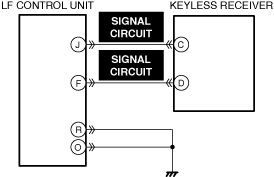
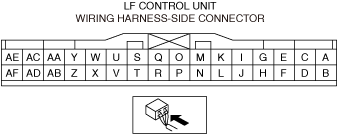
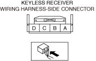
• Connector or terminal malfunction of the following parts:
• Short to ground or open circuit in keyless receiver signal circuit
• Keyless receiver malfunction
• LF control unit malfunction
|
|
 |
||
 |
 |
|
Diagnostic Procedure
|
Step |
Inspection |
Results |
Action |
|---|---|---|---|
|
1
|
VERIFY ALL SYSTEM DTCs
• Perform the DTC inspection. (See DTC INSPECTION.)
• Are any DTCs displayed?
|
Yes
|
Repair the malfunctioning location according to the applicable DTC troubleshooting.
|
|
No
|
Go to the next step.
|
||
|
2
|
INSPECT REMOTE TRANSMITTER FOR MALFUNCTION
• Inspect the applicable part. (See REMOTE TRANSMITTER BATTERY VOLTAGE INSPECTION.)
• Is the part normal?
|
Yes
|
Go to the next step.
|
|
No
|
Repair or replace the malfunctioning location and perform the repair completion verification.
|
||
|
3
|
DETERMINE IF MALFUNCTION CAUSE IS RADIO WAVE DISTURBANCE
• Did the malfunction occur under the following conditions?
|
Yes
|
The system is normal. (Explain to the customer that the operation cannot be performed due to radio wave disturbance.)
|
|
No
|
Go to the next step.
|
||
|
4
|
INSPECT KEYLESS RECEIVER AND LF CONTROL UNIT CONNECTORS FOR MALFUNCTION
• Inspect the applicable connector and terminal. (See CONNECTOR INSPECTION.)
• Are the connector and terminal normal?
|
Yes
|
Go to the next step.
|
|
No
|
Repair or replace the malfunctioning location and perform the repair completion verification.
|
||
|
5
|
INSPECT KEYLESS RECEIVER SIGNAL CIRCUIT FOR SHORT TO GROUND AND OPEN CIRCUIT
• Inspect the signal circuit for a short to ground and open circuit. (See CIRCUIT INSPECTION.)
• Is the circuit normal?
|
Yes
|
Go to the next step.
|
|
No
|
Repair or replace the malfunctioning location and perform the repair completion verification.
|
||
|
6
|
INSPECT KEYLESS RECEIVER FOR MALFUNCTION
• Inspect the applicable part. (See KEYLESS RECEIVER INSPECTION.)
• Is the part normal?
|
Yes
|
Go to the next step.
|
|
No
|
Repair or replace the malfunctioning location and perform the repair completion verification.
|
||
|
Repair completion verification
|
VERIFY THAT VEHICLE IS REPAIRED
• Install/connect the part removed/disconnected during the troubleshooting procedure.
• Has the malfunction symptom been eliminated?
|
Yes
|
Complete the symptom troubleshooting. (Explain contents of repair to customer)
|
|
No
|
Refer to the controller area network (CAN) malfunction diagnosis flow to inspect for a CAN communication error.
If the CAN communication is normal, perform the diagnosis from Step 1.
• If the malfunction is not resolved, replace the LF control unit. (See LF CONTROL UNIT REMOVAL/INSTALLATION.)
|