DTC U0323:00 [PCM (SKYACTIV-G)]
DTC U0323:00 [PCM (SKYACTIV-G)]
SM2334581
id0102t4901400
Outline
|
System malfunction location |
Instrument cluster error |
||||
|---|---|---|---|---|---|
|
Detection condition
|
• When any of the following conditions is met:
|
||||
|
Fail-safe
|
• Not applicable
|
||||
|
Possible cause
|
• CAN drive error (instrument cluster or PCM)
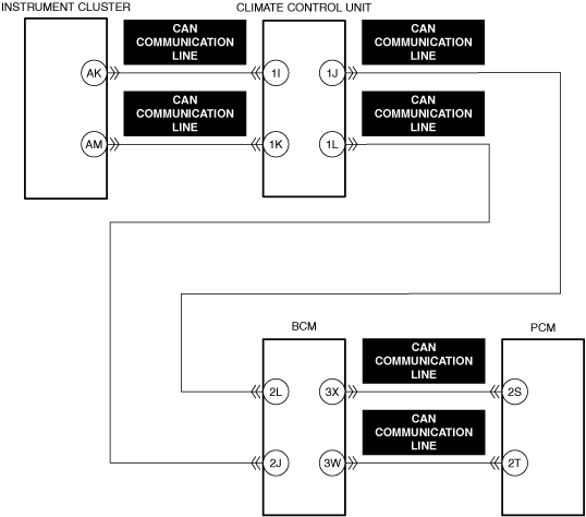
• CAN communication line malfunction between instrument cluster and PCM
• Instrument cluster connector or terminals malfunction
• PCM connector or terminals malfunction
• Instrument cluster malfunction
• PCM malfunction
|
||||
 |
|||||
 |
|||||
 |
 |
||||
 |
|||||
 |
|||||
Diagnostic Procedure
|
Step |
Inspection |
Results |
Action |
|---|---|---|---|
|
1
|
RECORD VEHICLE STATUS WHEN DTC WAS DETECTED TO UTILIZE WITH REPEATABILITY VERIFICATION
• Record the freeze frame data/snapshot data.
|
—
|
Go to the next step.
|
|
2
|
VERIFY RELATED REPAIR INFORMATION OR SERVICE INFORMATION AVAILABILITY
• Verify related Service Bulletins, on-line repair information, or Service Information availability.
• Is any related Information available?
|
Yes
|
Perform repair or diagnosis according to the available information.
• If the vehicle is not repaired, go to the next step.
|
|
No
|
Go to the next step.
|
||
|
3
|
INSPECT FOR OTHER RELATED DTCs
• Perform the DTC inspection for the PCM. (See DTC INSPECTION.)
• Are any other DTCs displayed?
|
Yes
|
Repair the malfunctioning location according to the applicable DTC troubleshooting.
|
|
No
|
Go to the next step.
|
||
|
4
|
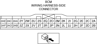
VERIFY BODY CONTROL MODULE (BCM) DTC
• Perform the DTC inspection for the body control module (BCM). (See DTC INSPECTION.)
• Are any DTCs displayed?
|
Yes
|
DTC U0100:00 is displayed:
• CAN communication line can be considered the cause.
DTC other than U0100:00 is displayed:
• Repair the malfunctioning location according to the applicable DTC troubleshooting. (See DTC TABLE [BODY CONTROL MODULE (BCM) (US)].)
|
|
No
|
Go to the next step.
|
||
|
5
|
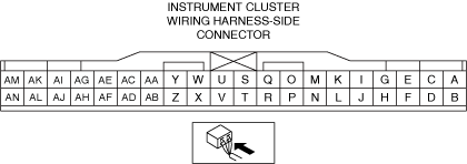
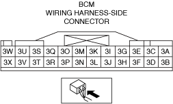
INSPECT INSTRUMENT CLUSTER CONNECTOR FOR MALFUNCTION
• Inspect the applicable connector and terminal. (See CONNECTOR INSPECTION.)
• Are the connector and terminal normal?
|
Yes
|
Go to the next step.
|
|
No
|
Repair or replace the malfunctioning location and perform the repair completion verification.
|
||
|
6
|
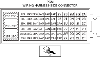
INSPECT PCM CONNECTOR FOR MALFUNCTION
• Inspect the applicable connector and terminal. (See CONNECTOR INSPECTION.)
• Are the connector and terminal normal?
|
Yes
|
Go to the next step.
|
|
No
|
Repair or replace the malfunctioning location and perform the repair completion verification.
|
||
|
Repair completion verification 1
|
VERIFY THAT VEHICLE IS REPAIRED
• Install/connect the part removed/disconnected during the troubleshooting procedure.
• Clear the DTC recorded in the memory. (See CLEARING DTC.)
• Replicate the vehicle conditions at the time the DTC was detected using the following procedure.
• Perform the DTC inspection for the PCM. (See DTC INSPECTION.)
• Is the same Pending DTC present?
|
Yes
|
Refer to the controller area network (CAN) malfunction diagnosis flow to inspect for a CAN communication error.
If the CAN communication is normal, perform the diagnosis from Step 1.
• If the malfunction recurs, replace the PCM, then go to the next step. (See PCM REMOVAL/INSTALLATION [SKYACTIV-G (WITH CYLINDER DEACTIVATION (US))].) (See PCM REMOVAL/INSTALLATION [SKYACTIV-G (WITHOUT CYLINDER DEACTIVATION (US))].)
|
|
No
|
Go to the next step.
|
||
|
Repair completion verification 2
|
VERIFY IF OTHER DTCs DISPLAYED
• Perform the DTC inspection. (See DTC INSPECTION.)
• Are any other DTCs displayed?
|
Yes
|
Repair the malfunctioning location according to the applicable DTC troubleshooting.
|
|
No
|
DTC troubleshooting completed.
|