DTC P26FE:00 [PCM (SKYACTIV-G)]
DTC P26FE:00 [PCM (SKYACTIV-G)]
SM2334484
id0102t4432500
-
Note
-
• To determine the malfunctioning part, proceed with the diagnostics from “Function Inspection Using M-MDS”.
Details On DTCs
|
Description |
Exhaust shutter valve range/performance problem |
||
|---|---|---|---|
|
Detection condition
|
Determination conditions
|
• If any of the following conditions is met under condition A or condition B:
|
|
|
Preconditions
|
Condition A:
• Battery voltage: above 8 V *1
Condition B:
• Battery voltage: above 8 V *1
• The input value from the exhaust shutter valve position sensor is in the closed valve side even though the PCM requests to operate the exhaust shutter valve to the open valve side.
• The following DTCs are not detected:
*1: Standard can be verified by displaying PIDs using M-MDS
|
||
|
Malfunction determination period
|
• 5 s period
|
||
|
Drive cycle
|
• 2
|
||
|
Self test type
|
• CMDTC self test, KOEO self test, KOER self test
|
||
|
Sensor used
|
• Exhaust shutter valve position sensor
|
||
|
Fail-safe function
|
• PCM restricts engine torque.
|
||
|
Vehicle status when dtcs are output
|
• Abnormal acceleration is occurring
• Booming noise from vehicle is occurring during cylinder deactivation control
|
||
|
Possible cause
|
• Exhaust shutter valve connector or terminals malfunction
• PCM connector or terminals malfunction
• Short to ground in exhaust shutter valve control circuit
• Short circuit in exhaust shutter valve control circuits
• Short to power supply in exhaust shutter valve control circuit
• Open circuit in exhaust shutter valve control circuit
• Exhaust shutter valve malfunction (valve stuck closed)
• PCM malfunction
|
||
 |
|||
 |
|||
 |
|||
Function Explanation (DTC Detection Outline)
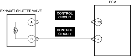
• The PCM calculates the target opening angle appropriate to the engine conditions relative to the actual opening angle based on the exhaust shutter valve position sensor signal and provides feedback to the exhaust shutter valve control.
• With the preconditions met, the PCM verifies the conformity of the actual opening angle relative to the target opening angle of the exhaust shutter valve. If the actual opening angle does not conform to the normal determination range relative to the target opening angle during the malfunction determination period ( approx. 5 s), the PCM determines a malfunction in the exhaust shutter valve and stores a DTC.
Repeatability Verification Procedure
• Not applicable
PID Item/Simulation Item Used In Diagnosis
• Not applicable
Function Inspection Using M-MDS
|
Step |
Inspection |
Results |
Action |
|---|---|---|---|
|
1
|
PURPOSE: VERIFY RELATED REPAIR INFORMATION OR SERVICE INFORMATION AVAILABILITY
• Verify related Service Bulletins, on-line repair information, or Service Information availability.
• Is any related Information available?
|
Yes
|
Perform repair or diagnosis according to the available information.
• If the vehicle is not repaired, go to the next step.
|
|
No
|
Go to the next step.
|
||
|
2
|
PURPOSE: RECORD VEHICLE STATUS WHEN DTC WAS DETECTED TO UTILIZE WITH REPEATABILITY VERIFICATION
• Record the freeze frame data/snapshot data.
|
—
|
Go to Troubleshooting Diagnostic Procedure to perform the procedure from Step 1.
|
Troubleshooting Diagnostic Procedure
Intention of troubleshooting procedure
• Step 1—6
-
― Perform an inspection of the connectors and wiring harnesses between the exhaust shutter valve and the PCM.
• Step 7
-
― Perform a unit inspection of the exhaust shutter valve.
• Repair completion verification
-
― Verify that the primary malfunction is resolved and there are no other malfunctions.
|
Step |
Inspection |
Results |
Action |
|---|---|---|---|
|
1
|
PURPOSE: INSPECT EXHAUST SHUTTER VALVE CONNECTOR FOR MALFUNCTION
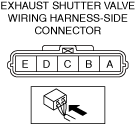
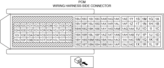
• Inspect the applicable connector and terminal. (See CONNECTOR INSPECTION.)
• Are the connector and terminal normal?
|
Yes
|
Go to the next step.
|
|
No
|
Repair or replace the malfunctioning location and perform the repair completion verification.
|
||
|
2
|
PURPOSE: INSPECT PCM CONNECTOR FOR MALFUNCTION
• Inspect the applicable connector and terminal. (See CONNECTOR INSPECTION.)
• Are the connector and terminal normal?
|
Yes
|
Go to the next step.
|
|
No
|
Repair or replace the malfunctioning location and perform the repair completion verification.
|
||
|
3
|
PURPOSE: INSPECT EXHAUST SHUTTER VALVE CONTROL CIRCUIT FOR SHORT TO GROUND
• Inspect the applicable circuit for a short to ground. (See CIRCUIT INSPECTION.)
• Is the circuit normal?
|
Yes
|
Go to the next step.
|
|
No
|
Repair or replace the malfunctioning location and perform the repair completion verification.
|
||
|
4
|
PURPOSE: INSPECT EXHAUST SHUTTER VALVE CONTROL CIRCUITS FOR SHORT CIRCUIT
• Inspect the applicable circuits for a short circuit. (See CIRCUIT INSPECTION.)
• Is the circuit normal?
|
Yes
|
Go to the next step.
|
|
No
|
Repair or replace the malfunctioning location and perform the repair completion verification.
|
||
|
5
|
PURPOSE: INSPECT EXHAUST SHUTTER VALVE CONTROL CIRCUIT FOR SHORT TO POWER SUPPLY
• Inspect the applicable circuit for a short to power supply. (See CIRCUIT INSPECTION.)
• Is the circuit normal?
|
Yes
|
Go to the next step.
|
|
No
|
Repair or replace the malfunctioning location and perform the repair completion verification.
|
||
|
6
|
PURPOSE: INSPECT EXHAUST SHUTTER VALVE CONTROL CIRCUIT FOR OPEN CIRCUIT
• Inspect the applicable circuit for open circuit. (See CIRCUIT INSPECTION.)
• Is the circuit normal?
|
Yes
|
Go to the next step.
|
|
No
|
Repair or replace the malfunctioning location and perform the repair completion verification.
|
||
|
7
|
PURPOSE: INSPECT EXHAUST SHUTTER VALVE FOR MALFUNCTION
• Inspect the applicable part. (See EXHAUST SHUTTER VALVE INSPECTION [SKYACTIV-G (WITH CYLINDER DEACTIVATION (US))].)
• Is the part normal?
|
Yes
|
Go to the next step.
|
|
No
|
Repair or replace the malfunctioning location and perform the repair completion verification.
|
||
|
Repair completion verification 1
|
PURPOSE: VERIFY THAT VEHICLE IS REPAIRED
• Install/connect the part removed/disconnected during the troubleshooting procedure.
• Clear the DTC recorded in the memory. (See CLEARING DTC.)
• Replicate the vehicle conditions at the time the DTC was detected using the following procedure.
• Perform the DTC inspection for the PCM. (See DTC INSPECTION.)
• Is the same Pending DTC present?
|
Yes
|
Refer to the controller area network (CAN) malfunction diagnosis flow to inspect for a CAN communication error.
If the CAN communication is normal, perform the diagnosis from Step 1.
• If the malfunction recurs, replace the PCM, then go to the next step. (See PCM REMOVAL/INSTALLATION [SKYACTIV-G (WITH CYLINDER DEACTIVATION (US))].)
|
|
No
|
Go to the next step.
|
||
|
Repair completion verification 2
|
PURPOSE: VERIFY IF OTHER DTCs DISPLAYED
• Perform the DTC inspection. (See DTC INSPECTION.)
• Are any other DTCs displayed?
|
Yes
|
Repair the malfunctioning location according to the applicable DTC troubleshooting.
|
|
No
|
DTC troubleshooting completed.
|