DTC B10A2:00 [PCM (SKYACTIV-G)]
DTC B10A2:00 [PCM (SKYACTIV-G)]
SM2334429
id0102t4215200
-
Note
-
• To determine the malfunctioning part, proceed with the diagnostics from “Function Inspection Using M-MDS”.
Details On DTCs
|
Description |
Vehicle collision |
|
|---|---|---|
|
Detection condition
|
Determination conditions
|
• A collision signal from the SAS control module is received.
|
|
Preconditions
|
• Not applicable.
|
|
|
Drive cycle
|
• 1
|
|
|
Self test type
|
• CMDTC self test
|
|
|
Sensor used
|
• PCM
|
|
|
Fail-safe function
|
• Stops fuel injection control
• Stops fuel pump control
• Stops ignition control
• Stops engine coolant fan control
|
|
|
Vehicle status when DTCs are output
|
• Stops fuel pump operation when ignition is switched ON
• Delays starter operation during cranking for maximum 1.2 s.
|
|
|
Possible cause
|
• Vehicle is involved in collision (collision signal from SAS control module is received)
• SAS control module malfunction
• PCM malfunction
|
|
System Wiring Diagram
• Not applicable
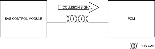
Function Explanation (DTC Detection Outline)
• During a collision, the SAS control module sends a collision signal to the PCM via the CAN signal. The PCM records a DTC by receiving a collision signal.
• This DTC does not indicate a part malfunction. It indicates operation of fail-safe from safety assurance during a vehicle collision.
am3zzw00033439
|
Repeatability Verification Procedure
1. Switch the ignition ON and leave for 5 s or more.
2. Clear the DTC from the PCM memory using the M-MDS. (See CLEARING DTC.)
3. After switching the ignition off, switch the ignition back ON and leave for 5 s or more.
4. Using the M-MDS, display DTCs and verify that DTC U0151:00 is not displayed. (See DTC INSPECTION.)
PID Item/Simulation Item Used In Diagnosis
• Not applicable
Function Inspection Using M-MDS
|
Step |
Inspection |
Results |
Action |
|---|---|---|---|
|
1
|
PURPOSE: RECORD VEHICLE STATUS WHEN DTC WAS DETECTED TO UTILIZE WITH REPEATABILITY VERIFICATION
• Record the freeze frame data/snapshot data.
|
—
|
Go to the next step.
|
|
2
|
PURPOSE: VERIFY RELATED REPAIR INFORMATION OR SERVICE INFORMATION AVAILABILITY
• Verify related Service Bulletins, on-line repair information, or Service Information availability.
• Is any related Information available?
|
Yes
|
Perform repair or diagnosis according to the available information.
• If the vehicle is not repaired, go to the next step.
|
|
No
|
Go to the next step.
|
||
|
3
|
PURPOSE: VERIFY IF OPERATION IS NORMAL AFTER VEHICLE COLLISION
• Ask customer about vehicle collision experience.
• Has the vehicle in for servicing been involved in a collision in which the air bag is deployed?
|
Yes
|
Explain to the customer that the DTC is recorded as a result of a vehicle collision.
Go to Troubleshooting Diagnostic Procedure to perform the procedure from Step 1.
|
|
No
|
Go to the next step.
|
||
|
4
|
PURPOSE: VERIFY SAS CONTROL MODULE DTC
• Perform the DTC inspection for the SAS control module. (See DTC INSPECTION.)
• Are any DTCs displayed?
|
Yes
|
Repair the malfunctioning location according to the applicable DTC troubleshooting.
Go to Troubleshooting Diagnostic Procedure to perform the procedure from Step 1.
|
|
No
|
Go to Troubleshooting Diagnostic Procedure to perform the procedure from Step 1.
|
Troubleshooting Diagnostic Procedure
Intention of troubleshooting procedure
• Step 1
• Repair completion verification
-
― Verify that the primary malfunction is resolved and there are no other malfunctions.
|
Step |
Inspection |
Results |
Action |
|---|---|---|---|
|
1
|
PURPOSE: PERFORM DTC INSPECTION AND VERIFY IF MALFUNCTIONING PART IS PCM
• Install/connect the part removed/disconnected during the troubleshooting procedure.
• Clear the DTC recorded in the memory. (See CLEARING DTC.)
• Replicate the vehicle conditions at the time the DTC was detected using the following procedure.
• Perform the DTC inspection for the PCM. (See DTC INSPECTION.)
• Is the same Pending DTC present?
|
Yes
|
Refer to the controller area network (CAN) malfunction diagnosis flow to inspect for a CAN communication error.
If the CAN communication is normal, perform the diagnosis from Step 1.
• If the malfunction recurs, replace the PCM, then go to the next step. (See PCM REMOVAL/INSTALLATION [SKYACTIV-G (WITH CYLINDER DEACTIVATION (US))].) (See PCM REMOVAL/INSTALLATION [SKYACTIV-G (WITHOUT CYLINDER DEACTIVATION (US))].)
|
|
No
|
Go to the next step.
|
||
|
Repair completion verification
|
PURPOSE: VERIFY IF OTHER DTCs DISPLAYED
• Perform the DTC inspection. (See DTC INSPECTION.)
• Are any other DTCs displayed?
|
Yes
|
Repair the malfunctioning location according to the applicable DTC troubleshooting.
|
|
No
|
DTC troubleshooting completed.
|