CONTROLLER AREA NETWORK (CAN) MALFUNCTION DIAGNOSIS FLOW [(US)]
CONTROLLER AREA NETWORK (CAN) MALFUNCTION DIAGNOSIS FLOW [(US)]
SM2566441
id1002x1000100
-
Note
-
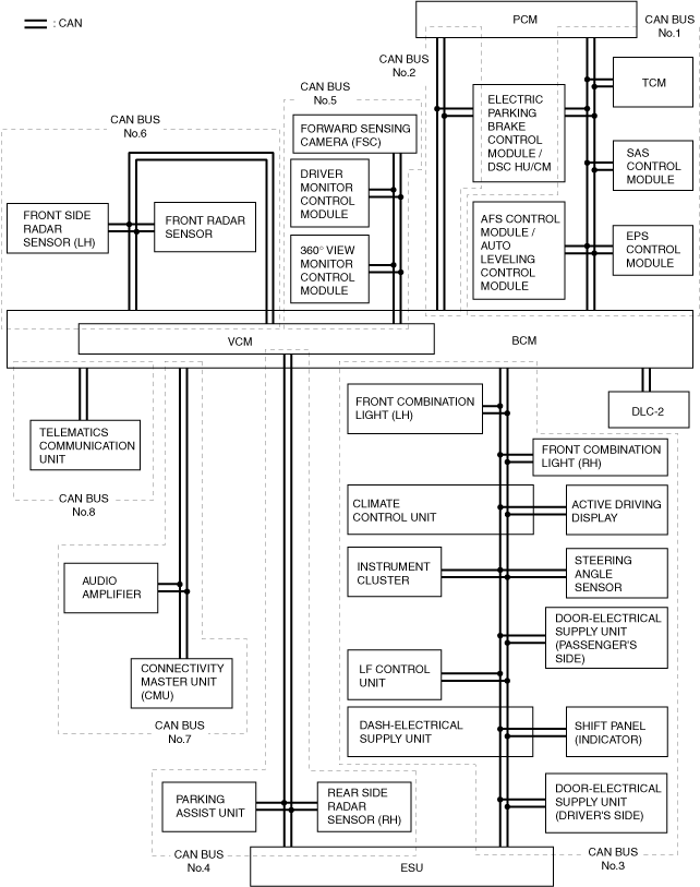
• It is necessary to select the CAN BUS to be diagnosed.Verify the module displayed in red (communication disabled) or blue (communication disabled or module not installed) from the network view on the M-MDS, and select any one CAN BUS between No.1 to 8.
CAN topology
 am3zzw00027501
1.Connect the M-MDS to the DLC-2.
2.Verify the module displayed in red or blue on the M-MDS using the network view.
3.Verify the applicable CAN BUS table and select the CAN BUS reference corresponding to the module displayed in red or blue on the M-MDS. (See CAN BUS table.)
-
Note
-
• The module may be displayed in red or blue on the M-MDS screen even if there is no malfunction depending on the vehicle specification.
CAN BUS table
Cross (×): module displayed in red or blue
|
CAN communication related module |
CAN BUS No.1 |
CAN BUS No.2 |
CAN BUS No.3 |
CAN BUS No.4 |
CAN BUS No.5 |
CAN BUS No.6 |
CAN BUS No.7 |
CAN BUS No.8 |
|---|---|---|---|---|---|---|---|---|
|
EPS control module
|
×
|
|||||||
|
AFS control module / auto leveling control module
|
×
|
|||||||
|
SAS control module
|
×
|
|||||||
|
Electric parking brake control module / DSC HU/CM
|
×
|
×
|
||||||
|
TCM
|
×
|
|||||||
|
PCM
|
×
|
×
|
||||||
|
Front combination light (LH)
|
×
|
|||||||
|
Front combination light (RH)
|
×
|
|||||||
|
Active driving display
|
×
|
|||||||
|
Climate control unit
|
×
|
|||||||
|
Steering angle sensor
|
×
|
|||||||
|
Instrument cluster
|
×
|
|||||||
|
Door-electrical supply unit (passenger’s side)
|
×
|
|||||||
|
LF control unit
|
×
|
|||||||
|
Shift panel (indicator)
|
×
|
|||||||
|
Dash-electrical supply unit
|
×
|
|||||||
|
Door-electrical supply unit (driver’s side)
|
×
|
|||||||
|
electrical supply unit (ESU)
|
×
|
×
|
||||||
|
Rear side radar sensor (RH)
|
×
|
|||||||
|
Parking assist unit
|
×
|
|||||||
|
360° view monitor control module
|
×
|
|||||||
|
Driver monitor control module
|
×
|
|||||||
|
Forward sensing camera (FSC)
|
×
|
|||||||
|
Front side radar sensor (LH)
|
×
|
|||||||
|
Front radar sensor
|
×
|
|||||||
|
Audio amplifier
|
×
|
|||||||
|
Connectivity master unit (CMU)
|
×
|
|||||||
|
Telematics communication unit
|
×
|
|||||||
|
Vehicle control module (VCM)
|
×
|
×
|
×
|
|||||
|
Body control module (BCM)
|
×
|
×
|
×
|
×
|
×
|
×
|
×
|
×
|
|
Diagnostic result
|
||||||||
|
CAN BUS reference
|
(See CAN-BUS No.1)
|
(See CAN-BUS No.2)
|
(See CAN-BUS No.3)
|
(See CAN-BUS No.4)
|
(See CAN-BUS No.5)
|
(See CAN-BUS No.6)
|
(See CAN-BUS No.7)
|
(See CAN-BUS No.8)
|
CAN-BUS No.1
-
Caution
-
• When disconnecting the connector, verify that there is no looseness, damage, deformation, corrosion, or poor connection of the connector terminals.• When inspecting the connector, touch it with a paper clip or similar thin pin without directly inserting a tester probe into the terminal.• Disconnect the negative battery terminal before performing any work that requires handling of connectors.
|
Step |
Inspection |
Action |
|
|---|---|---|---|
|
1
|
INSPECT FOR SHORT TO GROUND IN CAN-BUS NO.1
• Switch the ignition off.
• Disconnect the negative battery cable. (See NEGATIVE BATTERY TERMINAL DISCONNECTION/CONNECTION [(US)])
• Inspect for continuity at the following terminals:
• Is there continuity?
|
Yes
|
Short to ground in CAN-BUS No.1 has occurred.
Determine the location of a short to ground according to the diagnosis procedure for determining the location of a short to ground in CAN-BUS No.1.
|
|
No
|
Go to the next step.
|
||
|
2
|
INSPECT FOR SHORT TO POWER SUPPLY IN CAN-BUS No.1
• Connect the negative battery cable. (See NEGATIVE BATTERY TERMINAL DISCONNECTION/CONNECTION [(US)].)
• Switch the ignition ON (engine off).
• Measure the voltage at body control module (BCM) terminal 3X and 3W.
• Is the voltage between 1.5—3.5 V?
|
Yes
|
Go to the next step.
|
|
No
|
Short to power supply in CAN-BUS No.1 has occurred.
Determine the location of a short to power supply according to the diagnosis procedure for determining the location of a short to power supply in CAN-BUS No.1.
|
||
|
3
|
INSPECT FOR SHORT BETWEEN CIRCUITS IN CAN-BUS No.1
• Measure the voltage at body control module (BCM) terminals 3X and 3W.
• Is the voltage at body control module (BCM) terminals 3X and 3W the same?
|
Yes
|
Short between circuits in CAN-BUS No.1 has occurred.
Determine the location of a short between circuits according to the diagnosis procedure for determining the location of a short between circuits in CAN-BUS No.1.
|
|
No
|
An open circuit in CAN-BUS No.1 has occurred.
Determine the location of an open circuit in CAN-BUS No.1.
|
||
CAN-BUS No.2
-
Caution
-
• When disconnecting the connector, verify that there is no looseness, damage, deformation, corrosion, or poor connection of the connector terminals.• When inspecting the connector, touch it with a paper clip or similar thin pin without directly inserting a tester probe into the terminal.• Disconnect the negative battery terminal before performing any work that requires handling of connectors.
|
Step |
Inspection |
Action |
|
|---|---|---|---|
|
1
|
INSPECT FOR SHORT TO GROUND IN CAN-BUS No.2
• Switch the ignition off.
• Disconnect the negative battery cable. (See NEGATIVE BATTERY TERMINAL DISCONNECTION/CONNECTION [(US)])
• Inspect for continuity at the following terminals:
• Is there continuity?
|
Yes
|
Short to ground in CAN-BUS No.2 has occurred.
Determine the location of a short to ground according to the diagnosis procedure for determining the location of a short to ground in CAN-BUS No.2.
|
|
No
|
Go to the next step.
|
||
|
2
|
INSPECT FOR SHORT TO POWER SUPPLY IN CAN-BUS No.2
• Connect the negative battery cable. (See NEGATIVE BATTERY TERMINAL DISCONNECTION/CONNECTION [(US)].)
• Switch the ignition ON (engine off).
• Measure the voltage at body control module (BCM) terminal 2H and 2F.
• Is the voltage between 1.5—3.5 V?
|
Yes
|
Go to the next step.
|
|
No
|
Short to power supply in CAN-BUS No.2 has occurred.
Determine the location of a short to power supply according to the diagnosis procedure for determining the location of a short to power supply in CAN-BUS No.2.
|
||
|
3
|
INSPECT FOR SHORT BETWEEN CIRCUITS IN CAN-BUS No.2
• Measure the voltage at body control module (BCM) terminals 2H and 2F.
• Is the voltage at body control module (BCM) terminals 2H and 2F the same?
|
Yes
|
Short between circuits in CAN-BUS No.2 has occurred.
Determine the location of a short between circuits according to the diagnosis procedure for determining the location of a short between circuits in CAN-BUS No.2.
|
|
No
|
An open circuit in CAN-BUS No.2 has occurred.
Determine the location of an open circuit in CAN-BUS No.2.
|
||
CAN-BUS No.3
-
Caution
-
• When disconnecting the connector, verify that there is no looseness, damage, deformation, corrosion, or poor connection of the connector terminals.• When inspecting the connector, touch it with a paper clip or similar thin pin without directly inserting a tester probe into the terminal.• Disconnect the negative battery terminal before performing any work that requires handling of connectors.
|
Step |
Inspection |
Action |
|
|---|---|---|---|
|
1
|
INSPECT FOR SHORT TO GROUND IN CAN-BUS No.3
• Switch the ignition off.
• Disconnect the negative battery cable. (See NEGATIVE BATTERY TERMINAL DISCONNECTION/CONNECTION [(US)])
• Inspect for continuity at the following terminals:
• Is there continuity?
|
Yes
|
Short to ground in CAN-BUS No.3 has occurred.
Determine the location of a short to ground according to the diagnosis procedure for determining the location of a short to ground in CAN-BUS No.3.
|
|
No
|
Go to the next step.
|
||
|
2
|
INSPECT FOR SHORT TO POWER SUPPLY IN CAN-BUS No.3
• Connect the negative battery cable. (See NEGATIVE BATTERY TERMINAL DISCONNECTION/CONNECTION [(US)].)
• Switch the ignition ON (engine off).
• Measure the voltage at body control module (BCM) terminal 2L and 2J.
• Is the voltage between 1.5—3.5 V?
|
Yes
|
Go to the next step.
|
|
No
|
Short to power supply in CAN-BUS No.3 has occurred.
Determine the location of a short to power supply according to the diagnosis procedure for determining the location of a short to power supply in CAN-BUS No.3.
|
||
|
3
|
INSPECT FOR SHORT BETWEEN CIRCUITS IN CAN-BUS No.3
• Measure the voltage at body control module (BCM) terminals 2L and 2J.
• Is the voltage at body control module (BCM) terminals 2L and 2J the same?
|
Yes
|
Short between circuits in CAN-BUS No.3 has occurred.
Determine the location of a short between circuits according to the diagnosis procedure for determining the location of a short between circuits in CAN-BUS No.3.
|
|
No
|
An open circuit in CAN-BUS No.3 has occurred.
Determine the location of an open circuit in CAN-BUS No.3.
|
||
CAN-BUS No.4
-
Caution
-
• When disconnecting the connector, verify that there is no looseness, damage, deformation, corrosion, or poor connection of the connector terminals.• When inspecting the connector, touch it with a paper clip or similar thin pin without directly inserting a tester probe into the terminal.• Disconnect the negative battery terminal before performing any work that requires handling of connectors.
|
Step |
Inspection |
Action |
|
|---|---|---|---|
|
1
|
INSPECT FOR SHORT TO GROUND IN CAN-BUS No.4
• Switch the ignition off.
• Disconnect the negative battery cable. (See NEGATIVE BATTERY TERMINAL DISCONNECTION/CONNECTION [(US)])
• Inspect for continuity at the following terminals:
• Is there continuity?
|
Yes
|
Short to ground in CAN-BUS No.4 has occurred.
Determine the location of a short to ground according to the diagnosis procedure for determining the location of a short to ground in CAN-BUS No.4.
|
|
No
|
Go to the next step.
|
||
|
2
|
INSPECT FOR SHORT TO POWER SUPPLY IN CAN-BUS No.4
• Connect the negative battery cable. (See NEGATIVE BATTERY TERMINAL DISCONNECTION/CONNECTION [(US)].)
• Switch the ignition ON (engine off).
• Measure the voltage at body control module (BCM) terminal 2D and 2B.
• Is the voltage between 1.5—3.5 V?
|
Yes
|
Go to the next step.
|
|
No
|
Short to power supply in CAN-BUS No.4 has occurred.
Determine the location of a short to power supply according to the diagnosis procedure for determining the location of a short to power supply in CAN-BUS No.4.
|
||
|
3
|
INSPECT FOR SHORT BETWEEN CIRCUITS IN CAN-BUS No.4
• Measure the voltage at body control module (BCM) terminals 2D and 2B.
• Is the voltage at body control module (BCM) terminals 2D and 2B the same?
|
Yes
|
Short between circuits in CAN-BUS No.4 has occurred.
Determine the location of a short between circuits according to the diagnosis procedure for determining the location of a short between circuits in CAN-BUS No.4.
|
|
No
|
An open circuit in CAN-BUS No.4 has occurred.
Determine the location of an open circuit in CAN-BUS No.4.
|
||
CAN-BUS No.5
-
Caution
-
• When disconnecting the connector, verify that there is no looseness, damage, deformation, corrosion, or poor connection of the connector terminals.• When inspecting the connector, touch it with a paper clip or similar thin pin without directly inserting a tester probe into the terminal.• Disconnect the negative battery terminal before performing any work that requires handling of connectors.
|
Step |
Inspection |
Action |
|
|---|---|---|---|
|
1
|
INSPECT FOR SHORT TO GROUND IN CAN-BUS No.5
• Switch the ignition off.
• Disconnect the negative battery cable. (See NEGATIVE BATTERY TERMINAL DISCONNECTION/CONNECTION [(US)])
• Inspect for continuity at the following terminals:
• Is there continuity?
|
Yes
|
Short to ground in CAN-BUS No.5 has occurred.
Determine the location of a short to ground according to the diagnosis procedure for determining the location of a short to ground in CAN-BUS No.5.
|
|
No
|
Go to the next step.
|
||
|
2
|
INSPECT FOR SHORT TO POWER SUPPLY IN CAN-BUS No.5
• Connect the negative battery cable. (See NEGATIVE BATTERY TERMINAL DISCONNECTION/CONNECTION [(US)].)
• Switch the ignition ON (engine off).
• Measure the voltage at body control module (BCM) terminal 2E and 2G.
• Is the voltage between 1.5—3.5 V?
|
Yes
|
Go to the next step.
|
|
No
|
Short to power supply in CAN-BUS No.5 has occurred.
Determine the location of a short to power supply according to the diagnosis procedure for determining the location of a short to power supply in CAN-BUS No.5.
|
||
|
3
|
INSPECT FOR SHORT BETWEEN CIRCUITS IN CAN-BUS No.5
• Measure the voltage at body control module (BCM) terminals 2E and 2G.
• Is the voltage at body control module (BCM) terminals 2E and 2G the same?
|
Yes
|
Short between circuits in CAN-BUS No.5 has occurred.
Determine the location of a short between circuits according to the diagnosis procedure for determining the location of a short between circuits in CAN-BUS No.5.
|
|
No
|
An open circuit in CAN-BUS No.5 has occurred.
Determine the location of an open circuit in CAN-BUS No.5.
|
||
CAN-BUS No.6
-
Caution
-
• When disconnecting the connector, verify that there is no looseness, damage, deformation, corrosion, or poor connection of the connector terminals.• When inspecting the connector, touch it with a paper clip or similar thin pin without directly inserting a tester probe into the terminal.• Disconnect the negative battery terminal before performing any work that requires handling of connectors.
|
Step |
Inspection |
Action |
|
|---|---|---|---|
|
1
|
INSPECT FOR SHORT TO GROUND IN CAN-BUS No.6
• Switch the ignition off.
• Disconnect the negative battery cable. (See NEGATIVE BATTERY TERMINAL DISCONNECTION/CONNECTION [(US)])
• Inspect for continuity at the following terminals:
• Is there continuity?
|
Yes
|
Short to ground in CAN-BUS No.6 has occurred.
Determine the location of a short to ground according to the diagnosis procedure for determining the location of a short to ground in CAN-BUS No.6.
|
|
No
|
Go to the next step.
|
||
|
2
|
INSPECT FOR SHORT TO POWER SUPPLY IN CAN-BUS No.6
• Connect the negative battery cable. (See NEGATIVE BATTERY TERMINAL DISCONNECTION/CONNECTION [(US)].)
• Switch the ignition ON (engine off).
• Measure the voltage at body control module (BCM) terminal 2A and 2C.
• Is the voltage between 1.5—3.5 V?
|
Yes
|
Go to the next step.
|
|
No
|
Short to power supply in CAN-BUS No.6 has occurred.
Determine the location of a short to power supply according to the diagnosis procedure for determining the location of a short to power supply in CAN-BUS No.6.
|
||
|
3
|
INSPECT FOR SHORT BETWEEN CIRCUITS IN CAN-BUS No.6
• Measure the voltage at body control module (BCM) terminals 2A and 2C.
• Is the voltage at body control module (BCM) terminals 2A and 2C the same?
|
Yes
|
Short between circuits in CAN-BUS No.6 has occurred.
Determine the location of a short between circuits according to the diagnosis procedure for determining the location of a short between circuits in CAN-BUS No.6.
|
|
No
|
An open circuit in CAN-BUS No.6 has occurred.
Determine the location of an open circuit in CAN-BUS No.6.
|
||
CAN-BUS No.7
-
Caution
-
• When disconnecting the connector, verify that there is no looseness, damage, deformation, corrosion, or poor connection of the connector terminals.• When inspecting the connector, touch it with a paper clip or similar thin pin without directly inserting a tester probe into the terminal.• Disconnect the negative battery terminal before performing any work that requires handling of connectors.
|
Step |
Inspection |
Action |
|
|---|---|---|---|
|
1
|
INSPECT FOR SHORT TO GROUND IN CAN-BUS No.7
• Switch the ignition off.
• Disconnect the negative battery cable. (See NEGATIVE BATTERY TERMINAL DISCONNECTION/CONNECTION [(US)])
• Inspect for continuity at the following terminals:
• Is there continuity?
|
Yes
|
Short to ground in CAN-BUS No.7 has occurred.
Determine the location of a short to ground according to the diagnosis procedure for determining the location of a short to ground in CAN-BUS No.7.
|
|
No
|
Go to the next step.
|
||
|
2
|
INSPECT FOR SHORT TO POWER SUPPLY IN CAN-BUS No.7
• Connect the negative battery cable. (See NEGATIVE BATTERY TERMINAL DISCONNECTION/CONNECTION [(US)].)
• Switch the ignition ON (engine off).
• Measure the voltage at body control module (BCM) terminal 4R and 4Q.
• Is the voltage between 1.5—3.5 V?
|
Yes
|
Go to the next step.
|
|
No
|
Short to power supply in CAN-BUS No.7 has occurred.
Determine the location of a short to power supply according to the diagnosis procedure for determining the location of a short to power supply in CAN-BUS No.7.
|
||
|
3
|
INSPECT FOR SHORT BETWEEN CIRCUITS IN CAN-BUS No.7
• Measure the voltage at body control module (BCM) terminals 4R and 4Q.
• Is the voltage at body control module (BCM) terminals 4R and 4Q the same?
|
Yes
|
Short between circuits in CAN-BUS No.7 has occurred.
Determine the location of a short between circuits according to the diagnosis procedure for determining the location of a short between circuits in CAN-BUS No.7.
|
|
No
|
An open circuit in CAN-BUS No.7 has occurred.
Determine the location of an open circuit in CAN-BUS No.7.
|
||
CAN-BUS No.8
-
Caution
-
• When disconnecting the connector, verify that there is no looseness, damage, deformation, corrosion, or poor connection of the connector terminals.• When inspecting the connector, touch it with a paper clip or similar thin pin without directly inserting a tester probe into the terminal.• Disconnect the negative battery terminal before performing any work that requires handling of connectors.
|
Step |
Inspection |
Action |
|
|---|---|---|---|
|
1
|
INSPECT FOR SHORT TO GROUND IN CAN-BUS No.8
• Switch the ignition off.
• Disconnect the negative battery cable. (See NEGATIVE BATTERY TERMINAL DISCONNECTION/CONNECTION [(US)])
• Inspect for continuity at the following terminals:
• Is there continuity?
|
Yes
|
Short to ground in CAN-BUS No.8 has occurred.
Determine the location of a short to ground according to the diagnosis procedure for determining the location of a short to ground in CAN-BUS No.8.
|
|
No
|
Go to the next step.
|
||
|
2
|
INSPECT FOR SHORT TO POWER SUPPLY IN CAN-BUS No.8
• Connect the negative battery cable. (See NEGATIVE BATTERY TERMINAL DISCONNECTION/CONNECTION [(US)].)
• Switch the ignition ON (engine off).
• Measure the voltage at body control module (BCM) terminal 3U and 3V.
• Is the voltage between 1.5—3.5 V?
|
Yes
|
Go to the next step.
|
|
No
|
Short to power supply in CAN-BUS No.8 has occurred.
Determine the location of a short to power supply according to the diagnosis procedure for determining the location of a short to power supply in CAN-BUS No.8.
|
||
|
3
|
INSPECT FOR SHORT BETWEEN CIRCUITS IN CAN-BUS No.8
• Measure the voltage at body control module (BCM) terminals 3U and 3V.
• Is the voltage at body control module (BCM) terminals 3U and 3V the same?
|
Yes
|
Short between circuits in CAN-BUS No.8 has occurred.
Determine the location of a short between circuits according to the diagnosis procedure for determining the location of a short between circuits in CAN-BUS No.8.
|
|
No
|
An open circuit in CAN-BUS No.8 has occurred.
Determine the location of an open circuit in CAN-BUS No.8.
|
||