Menu +
Generic selectors
Exact matches only
Search in title
Search in content
Post Type Selectors

SECURITY INDICATOR LIGHT: 13, DTC: B13D3:94/P1260:00 [START STOP UNIT]

< Previous Next >

2016 – MX-5 – Body and Accessories

SECURITY INDICATOR LIGHT: 13, DTC: B13D3:94/P1260:00 [START STOP UNIT]

Description

Communication error with remote transmitter

Detection condition

  • Start stop unit could not detect the remote transmitter communication or communication error was detected.

Fail-safe

Not applicable

Possible cause

  • When the ignition is switched ON (engine off or on), it is detected that the remote transmitter is outside of the vehicle.

  • Keyless receiver malfunction

  • Push button start connector or terminal malfunction

  • Keyless receiver connector or terminal malfunction

  • Start stop unit connector or terminal malfunction

  • Open circuit in wiring harness between the following terminals:

    • Start stop unit terminal 2Q—Keyless receiver terminal A

    • Start stop unit terminal 2R—Keyless receiver terminal B

  • Remote transmitter battery power low

  • Remote transmitter malfunction

  • Start stop unit malfunction

NOTE:

  • If any of the following items are touching or near the remote transmitter, signal communication between the remote transmitter and the vehicle is negatively affected, resulting in the engine not starting.

    • Spare keys

    • Keys for other vehicles equipped with an immobilizer system

    • Any metallic object

    • Any electronic device, or any credit or other card with magnetic strips

    • Radio wave outputting device nearby

Diagnostic Procedure

Step

Inspection

Action

1

VERIFY DTCs WITH REMOTE TRANSMITTER IN DIFFERENT LOCATIONS

  • Clear the DTC for the start stop unit using the M-MDS.

    (See CLEARING DTC [START STOP UNIT].)

  • Perform the following procedure 3 times with the remote transmitter inside the cabin with certainty.

    • Switch the ignition off.

    • Switch the ignition ON (engine off or on).

    • Retrieve the start stop unit DTCs using the M-MDS.

      (See DTC INSPECTION [START STOP UNIT].)

    • Move the remote transmitter to a different location.

  • Is the security indicator light: 13, DTC B13D3:94/P1260:00 displayed?

Yes

Go to the next step.

No

Go to Step 10.

2

PERFORM DTC INSPECTION AND VERIFY KEYLESS RECEIVER MALFUNCTION

Yes

Repair or replace the malfunctioning part according to the applicable DTC troubleshooting.

(See DTC TABLE [START STOP UNIT].)

No

Go to the next step.

3

INSPECT PUSH BUTTON START CONNECTOR CONDITION

  • Switch the ignition off.

  • Disconnect the negative battery cable.

    (See NEGATIVE BATTERY CABLE DISCONNECTION/CONNECTION.)

  • Disconnect the push button start connector.

  • Inspect the connector engagement and connection condition and inspect the terminals for damage, deformation, corrosion, or disconnection.

  • Is the connector normal?

Yes

Go to the next step.

No

Repair or replace the connector, then go to Step 9.

4

INSPECT KEYLESS RECEIVER CONNECTOR CONDITION

  • Disconnect the keyless receiver connector.

  • Inspect the connector engagement and connection condition and inspect the terminals for damage, deformation, corrosion, or disconnection.

  • Is the connector normal?

Yes

Go to the next step.

No

Repair or replace the connector, then go to Step 9.

5

INSPECT START STOP UNIT CONNECTOR CONDITION

  • Disconnect the start stop unit connector.

  • Inspect the connector engagement and connection condition and inspect the terminals for damage, deformation, corrosion, or disconnection.

  • Is the connector normal?

Yes

Go to the next step.

No

Repair or replace the connector, then go to Step 9.

6

INSPECT KEYLESS RECEIVER CIRCUIT FOR OPEN CIRCUIT

  • Verify that the start stop unit and keyless receiver connectors are disconnected.

  • Inspect for continuity between the following terminals (wiring harness-side):

    • Start stop unit terminal 2Q—Keyless receiver terminal A

    • Start stop unit terminal 2R—Keyless receiver terminal B

  • Is there continuity?

Yes

Go to the next step.

No

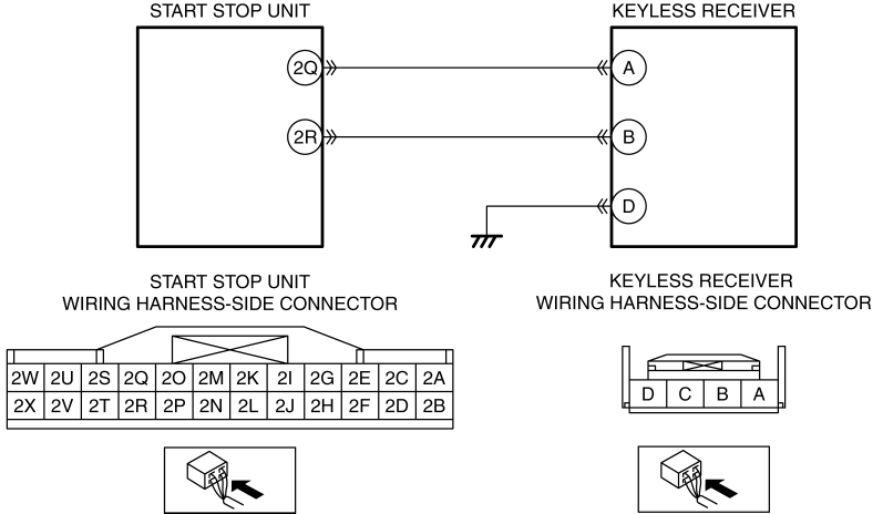
Refer to the wiring diagram and verify whether or not there is a common connector between the following terminals:

  • Start stop unit terminal 2Q—Keyless receiver terminal A

  • Start stop unit terminal 2R—Keyless receiver terminal B

    If there is a common connector:

  • Determine the malfunctioning part by inspecting the common connector and the terminal for corrosion, damage, or pin disconnection, and the common wiring harness for an open circuit.

  • Repair or replace the malfunctioning part.

    If there is no common connector:

  • Repair or replace the wiring harness which has an open circuit.

Go to Step 9.

7

INSPECT REMOTE TRANSMITTER BATTERY POWER

Yes

NOTE:

  • If the KEY indicator light (green) flashes for approx. 30 s, the battery power of the remote transmitter is low.

Replace the remote transmitter battery and go to Step 9.

(See REMOTE TRANSMITTER DISASSEMBLY/ASSEMBLY.)

No

Go to the next step.

8

VERIFY IF MALFUNCTION CAUSE IS REMOTE TRANSMITTER

Yes

Replace the remote transmitter, then go to the next step.

(See IMMOBILIZER SYSTEM-RELATED PARTS PROGRAMMING.)

No

Go to Step 10.

9

VERIFY THAT REPAIRS HAVE BEEN COMPLETED

Yes

Repeat the inspection from Step 1.

Go to the next step.

No

Go to the next step.

10

VERIFY IF OTHER DTCs DISPLAYED

  • Are any other DTCs displayed?

Yes

Repair or replace the malfunctioning part according to the applicable DTC troubleshooting.

(See DTC TABLE [START STOP UNIT].)

No

DTC troubleshooting completed.

< Previous Next >

© 2014 Mazda North American Operations, U.S.A.