DTC P0031:00 [PCM (SKYACTIV-G 2.0)]
2016 – MX-5 – Engine
DTC P0031:00 [PCM (SKYACTIV-G 2.0)]
|
DTC P0031:00 |
A/F sensor heater control circuit low input |
|
DETECTION CONDITION |
|
|
FAIL-SAFE FUNCTION |
|
|
POSSIBLE CAUSE |
|
|
|
|
Diagnostic Procedure
|
STEP |
INSPECTION |
ACTION |
|
|
1 |
RECORD FREEZE FRAME DATA/SNAPSHOT DATA AND DIAGNOSTIC MONITORING TEST RESULTS TO UTILIZE WITH REPEATABILITY VERIFICATION
NOTE:
|
— |
Go to the next step. |
|
2 |
VERIFY RELATED REPAIR INFORMATION AVAILABILITY
|
Yes |
Perform repair or diagnosis according to the available repair information.
|
|
No |
Go to the next step. |
||
|
3 |
INSPECT A/F SENSOR CONNECTOR CONDITION
|
Yes |
Repair or replace the connector and/or terminals, then go to Step 9. |
|
No |
Go to the next step. |
||
|
4 |
INSPECT A/F SENSOR HEATER POWER SUPPLY CIRCUIT FOR SHORT TO GROUND OR OPEN CIRCUIT
|
Yes |
Go to the next step. |
|
No |
Inspect the ENGINE1 10 A fuse.
Go to Step 9. |
||
|
5 |
INSPECT PCM CONNECTOR CONDITION
|
Yes |
Repair or replace the connector and/or terminals, then go to Step 9. |
|
No |
Go to the next step. |
||
|
6 |
INSPECT A/F SENSOR HEATER CONTROL CIRCUIT FOR SHORT TO GROUND
|
Yes |
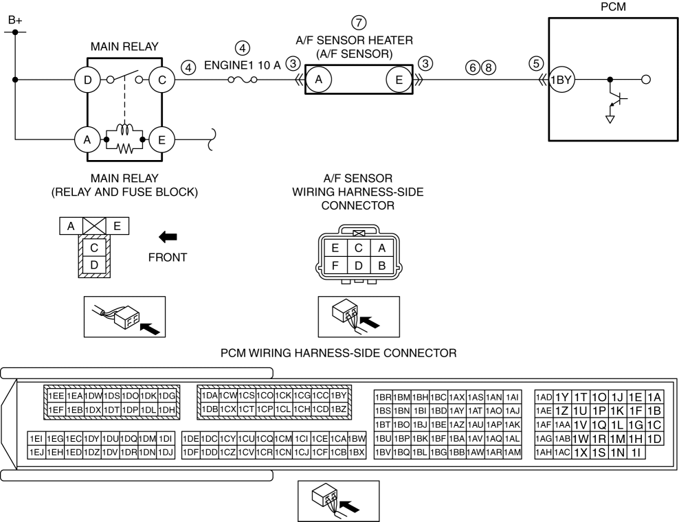
Refer to the wiring diagram and verify whether or not there is a common connector between A/F sensor terminal E and PCM terminal 1BY.
Go to Step 9. |
|
No |
Go to the next step. |
||
|
7 |
INSPECT A/F SENSOR HEATER
|
Yes |
Replace the A/F sensor, then go to Step 9. (See AIR FUEL RATIO (A/F) SENSOR REMOVAL/INSTALLATION [SKYACTIV-G 2.0].) |
|
No |
Go to the next step. |
||
|
8 |
INSPECT A/F SENSOR HEATER CONTROL CIRCUIT FOR OPEN CIRCUIT
|
Yes |
Go to the next step. |
|
No |
Refer to the wiring diagram and verify whether or not there is a common connector between A/F sensor terminal E and PCM terminal 1BY.
Go to the next step. |
||
|
9 |
VERIFY DTC TROUBLESHOOTING COMPLETED
|
Yes |
Repeat the inspection from Step 1.
Go to the next step. |
|
No |
Go to the next step. |
||
|
10 |
VERIFY AFTER REPAIR PROCEDURE
|
Yes |
Go to the applicable DTC inspection. |
|
No |
DTC troubleshooting completed. |
||