DETERMINING SHORT TO POWER SUPPLY LOCATION (CAN-BUS No.8) [(US)]
DETERMINING SHORT TO POWER SUPPLY LOCATION (CAN-BUS No.8) [(US)]
SM2566473
id1002x1004700
-
Caution
-
• Perform the following malfunction diagnosis only when it is diagnosed with a short to ground by CONTROLLER AREA NETWORK (CAN) MALFUNCTION DIAGNOSIS FLOW. (See CONTROLLER AREA NETWORK (CAN) MALFUNCTION DIAGNOSIS FLOW [(US)].)
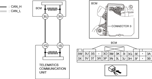
System Wiring Diagram
am3zzw00027519
|
Determination Procedure
-
Caution
-
• When disconnecting the connector, verify that there is no looseness, damage, deformation, corrosion, or poor connection of the connector terminals.• When inspecting the connector, touch it with a paper clip or similar thin pin without directly inserting a tester probe into the terminal.• Disconnect the negative battery cable before performing any work that requires handling of connectors.
|
Step |
Inspection |
Action |
|
|---|---|---|---|
|
1
|
INSPECT CAN LINE BETWEEN BODY CONTROL MODULE (BCM) AND TELEMATICS COMMUNICATION UNIT FOR SHORT TO POWER SUPPLY
• Switch the ignition off.
• Disconnect the negative battery cable. (See NEGATIVE BATTERY TERMINAL DISCONNECTION/CONNECTION [(US)].)
• Disconnect the connector 3 which has body control module (BCM) terminals 3U and 3W.
• Connect the negative battery cable. (See NEGATIVE BATTERY TERMINAL DISCONNECTION/CONNECTION [(US)].)
• Switch the ignition ON (engine off).
• Measure the voltage at body control module (BCM) terminals 3U and 3V (wiring harness side).
• Is the voltage between 1.5—3.5 V?
|
Yes
|
Replace the body control module (BCM) because there is a short to the power supply in the body control module (BCM).
|
|
No
|
Go to the next step.
|
||
|
2
|
INSPECT TELEMATICS COMMUNICATION UNIT FOR SHORT TO POWER SUPPLY
• Switch the ignition off.
• Disconnect the negative battery cable. (See NEGATIVE BATTERY TERMINAL DISCONNECTION/CONNECTION [(US)].)
• Disconnect the telematics communication unit connector.
• Connect the connector 3 which has body control module (BCM) terminals 3U and 3W.
• Connect the negative battery cable. (See NEGATIVE BATTERY TERMINAL DISCONNECTION/CONNECTION [(US)].)
• Switch the ignition ON (engine off).
• Measure the voltage at body control module (BCM) terminals 3U and 3V.
• Is the voltage between 1.5—3.5 V?
|
Yes
|
Replace the telematics communication unit because there is a short to the power supply in the telematics communication unit.
|
|
No
|
Repair or replace the wiring harness between the telematics communication unit and body control module (BCM) because the wiring harness is shorted to the power supply.
|
||