DETERMINING OPEN CIRCUIT LOCATION (CAN-BUS No.1) [(US)]
DETERMINING OPEN CIRCUIT LOCATION (CAN-BUS No.1) [(US)]
SM2566443
id1002x1001700
-
Caution
-
• Perform the following malfunction diagnosis only when it is diagnosed with a open circuit by CONTROLLER AREA NETWORK (CAN) MALFUNCTION DIAGNOSIS FLOW. (See CONTROLLER AREA NETWORK (CAN) MALFUNCTION DIAGNOSIS FLOW [(US)].)• If the malfunctioning part is detected in the communication line, before disconnecting the related connector for inspection, press the connector in the connection direction to verify that there is no looseness or disconnection.• When disconnecting the connector, verify that there is no damage, deformation, or corrosion of the connector terminals.
1.Verify the CAN system-related module DTCs and the module displayed in red or blue on the M-MDS screen.
2.Apply the communication error DTC and the module displayed in red or blue to the DTC output pattern and malfunctioning location, and select the possible cause for the diagnostic result and the reference for the inspection item. (See DTC Output Pattern And Malfunctioning Location)
-
Note
-
• The open circuit location can be determined by the DTC indicated in the DTC output pattern and malfunctioning location chart. DTCs not listed in the chart are not used for the determination of the open circuit location. (See DTC Output Pattern And Malfunctioning Location.)• The module may be displayed in red or blue on the M-MDS screen even if there is no malfunction depending on the vehicle specification.
3.Inspect the possible cause and inspection item of the applicable malfunctioning part.
DTC Output Pattern And Malfunctioning Location
Cross (×): Communication error-related DTC
|
M-MDS display |
DTC |
DTC output pattern and malfunctioning location |
|||||||||
|---|---|---|---|---|---|---|---|---|---|---|---|
|
DTC output module |
|||||||||||
|
PCM
|
U0101:00
|
×
|
|||||||||
|
U0121:00
|
×
|
||||||||||
|
U0131:00
|
×
|
||||||||||
|
U0140:00
|
|||||||||||
|
U0151:00
|
×
|
||||||||||
|
U0155:00
|
|||||||||||
|
U0164:00
|
|||||||||||
|
U2121:00
|
|||||||||||
|
U212E:00
|
|||||||||||
|
U2131:00
|
|||||||||||
|
U2133:00
|
|||||||||||
|
DSC HU/CM
|
U0100:00
|
×
|
×
|
||||||||
|
U0101:00
|
×
|
×
|
|||||||||
|
U0131:00
|
×
|
||||||||||
|
U0140:00
|
|||||||||||
|
U0151:00
|
×
|
||||||||||
|
U0155:00
|
|||||||||||
|
U0164:00
|
|||||||||||
|
U2121:00
|
|||||||||||
|
U212E:00
|
|||||||||||
|
U2131:00
|
|||||||||||
|
EPS control module
|
U0100:00
|
×
|
×
|
×
|
×
|
||||||
|
U0121:00
|
×
|
×
|
×
|
||||||||
|
U0140:00
|
×
|
||||||||||
|
U2121:00
|
|||||||||||
|
Vehicle control module (VCM)
|
U0100:00
|
×
|
×
|
×
|
×
|
×
|
|||||
|
U0101:00
|
×
|
×
|
×
|
×
|
×
|
||||||
|
U0121:00
|
×
|
×
|
×
|
×
|
|||||||
|
U0126:00
|
|||||||||||
|
U0131:00
|
×
|
×
|
|||||||||
|
U0140:00
|
|||||||||||
|
U0151:00
|
×
|
×
|
×
|
||||||||
|
U0155:00
|
|||||||||||
|
U0156:00
|
|||||||||||
|
U0164:00
|
|||||||||||
|
U2120:00
|
|||||||||||
|
U2122:00
|
|||||||||||
|
U2123:00
|
|||||||||||
|
U2125:00
|
|||||||||||
|
U2126:00
|
|||||||||||
|
U212E:00
|
|||||||||||
|
U2131:00
|
|||||||||||
|
U2132:00
|
|||||||||||
|
U2133:00
|
|||||||||||
|
U2139:00
|
|||||||||||
|
U213A:00
|
|||||||||||
|
Body control module (BCM)
|
U0100:00
|
×
|
×
|
×
|
×
|
×
|
|||||
|
U0101:00
|
×
|
×
|
×
|
×
|
×
|
||||||
|
U0115:00
|
×
|
×
|
×
|
×
|
×
|
||||||
|
U0121:00
|
×
|
×
|
×
|
×
|
|||||||
|
U0121:87
|
×
|
×
|
×
|
×
|
|||||||
|
U0126:00
|
|||||||||||
|
U0131:00
|
×
|
×
|
|||||||||
|
U0151:00
|
×
|
×
|
×
|
||||||||
|
U0155:00
|
|||||||||||
|
U0156:00
|
|||||||||||
|
U0158:00
|
|||||||||||
|
U0164:00
|
|||||||||||
|
U0182:00
|
×
|
×
|
|||||||||
|
U2121:49
|
|||||||||||
|
U212A:00
|
|||||||||||
|
U212C:00
|
|||||||||||
|
U212D:00
|
|||||||||||
|
U212E:00
|
|||||||||||
|
U2131:00
|
|||||||||||
|
U2133:00
|
|||||||||||
|
U213A:00
|
|||||||||||
|
U213B:00
|
|||||||||||
|
U213C:00
|
×
|
×
|
×
|
×
|
|||||||
|
Connectivity master unit (CMU)
|
U0140:00
|
||||||||||
|
Telematics communication unit
|
U0140:00
|
||||||||||
|
U0151:00
|
×
|
×
|
|||||||||
|
U0164:00
|
|||||||||||
|
U213C:00
|
×
|
×
|
×
|
||||||||
|
Adaptive front lighting system (AFS) control module
|
U0122:87
|
×
|
×
|
×
|
|||||||
|
U0126:87
|
|||||||||||
|
U212A:87
|
|||||||||||
|
U212B:87
|
|||||||||||
|
U212D:87
|
|||||||||||
|
Dash-electrical supply unit
|
U0100:00
|
×
|
×
|
×
|
×
|
×
|
|||||
|
U0101:00
|
×
|
×
|
×
|
×
|
×
|
||||||
|
U0121:00
|
×
|
×
|
×
|
×
|
|||||||
|
U0151:00
|
×
|
×
|
×
|
||||||||
|
U212B:00
|
|||||||||||
|
U212E:00
|
|||||||||||
|
U2131:00
|
|||||||||||
|
U2133:00
|
|||||||||||
|
U213A:00
|
|||||||||||
|
SAS control module
|
U0140:00
|
||||||||||
|
U0155:00
|
|||||||||||
|
U0156:00
|
|||||||||||
|
TCM
|
U0100:00
|
×
|
|||||||||
|
U0121:00
|
×
|
||||||||||
|
U0131:00
|
×
|
||||||||||
|
U0140:00
|
|||||||||||
|
U0155:00
|
|||||||||||
|
U212C:00
|
|||||||||||
|
M-MDS display module
|
Module displayed in red or blue
|
||||||||||
|
PCM
|
×
|
×
|
×
|
×
|
×
|
||||||
|
TCM
|
×
|
×
|
×
|
×
|
×
|
||||||
|
DSC HU/CM
|
×
|
×
|
×
|
×
|
|||||||
|
SAS control module
|
×
|
×
|
×
|
||||||||
|
AFS control module / auto leveling control module
|
×
|
×
|
|||||||||
|
EPS control module
|
×
|
×
|
|||||||||
|
Diagnostic result
|
|||||||||||
|
Possible cause and inspection item
|
|||||||||||
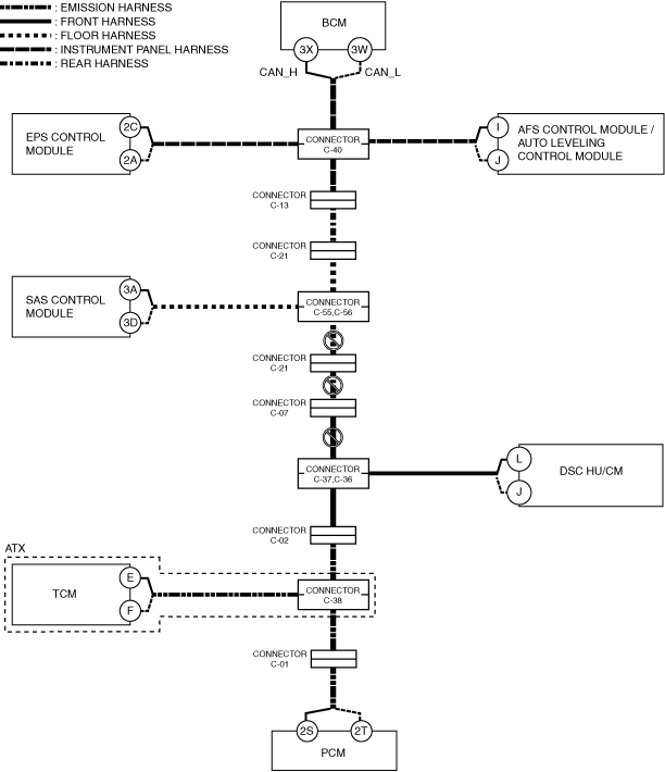
A
ATX
-
Possible cause
-
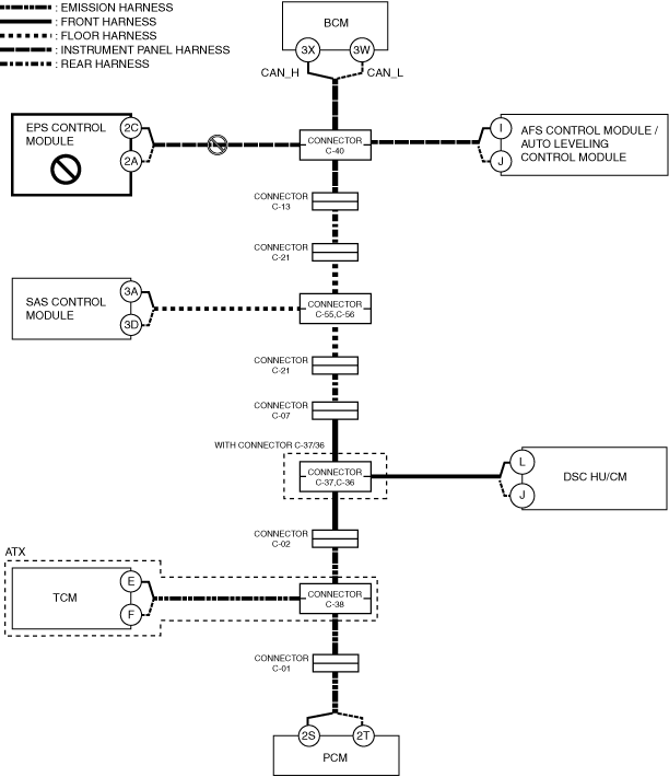
• Connector terminal disconnection, poor contact, damage, deformation, corrosion• PCM power supply voltage or body ground malfunction• Open circuit in wiring harness between PCM and connector C-01• Open circuit in wiring harness between connector C-01 and connector C-38• Connector C-01 malfunction• Connector C-38 malfunction• PCM malfunction
System wiring diagram
am3zzw00027584
|
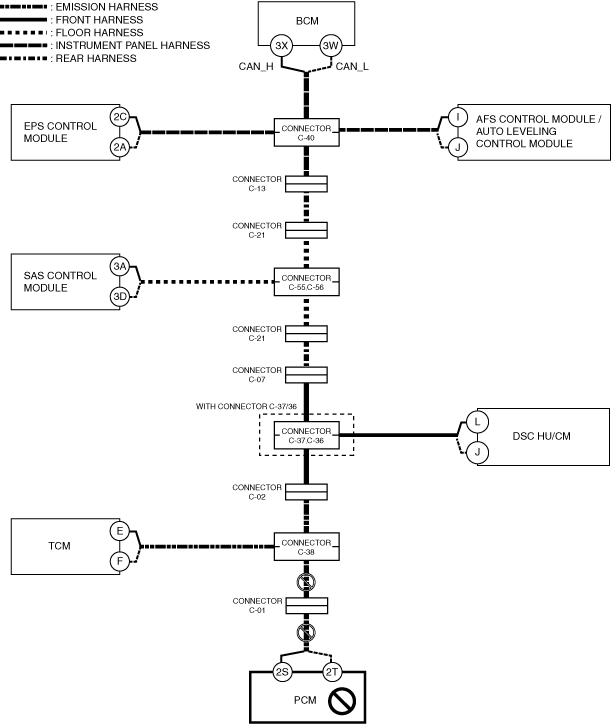
-
Inspection item
-
• PCM power supply voltage-related wiring harness and fuse• PCM body ground related wiring harness• PCM connector• Connector C-01• Connector C-38• Wiring harness between PCM terminal 2S and connector C-01• Wiring harness between PCM terminal 2T and connector C-01• Wiring harness between connector C-01 and connector C-38• PCM
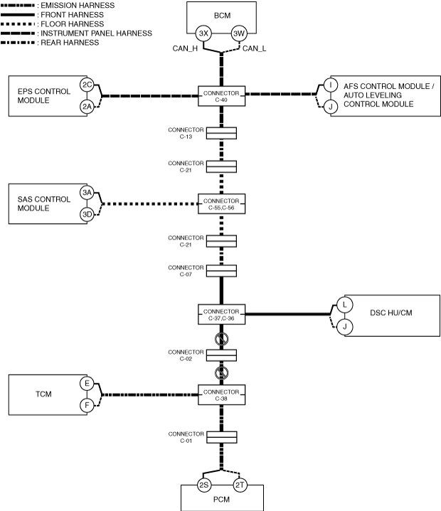
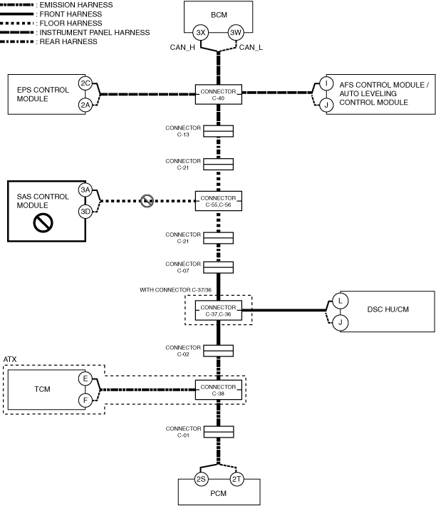
MTX (with connectors C-37, C-36)
-
Possible cause
-
• Connector terminal disconnection, poor contact, damage, deformation, corrosion• PCM power supply voltage or body ground malfunction• Open circuit in wiring harness between PCM and connector C-01• Open circuit in wiring harness between connector C-01 and connector C-02• Open circuit in wiring harness between connector C-02 and connectors C-37, C-36• Connector C-01 malfunction• Connector C-02 malfunction• Connectors C-37, C-36 malfunction• PCM malfunction
System wiring diagram
am3zzw00027585
|
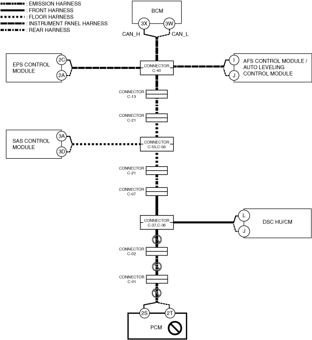
-
Inspection item
-
• PCM power supply voltage-related wiring harness and fuse• PCM body ground related wiring harness• PCM connector• Connector C-01• Connector C-02• Connectors C-37, C-36• Wiring harness between PCM terminal 2S and connector C-01• Wiring harness between PCM terminal 2T and connector C-01• Wiring harness between connector C-01 and connector C-02• Wiring harness between connector C-02 and connectors C-37, C-36• PCM
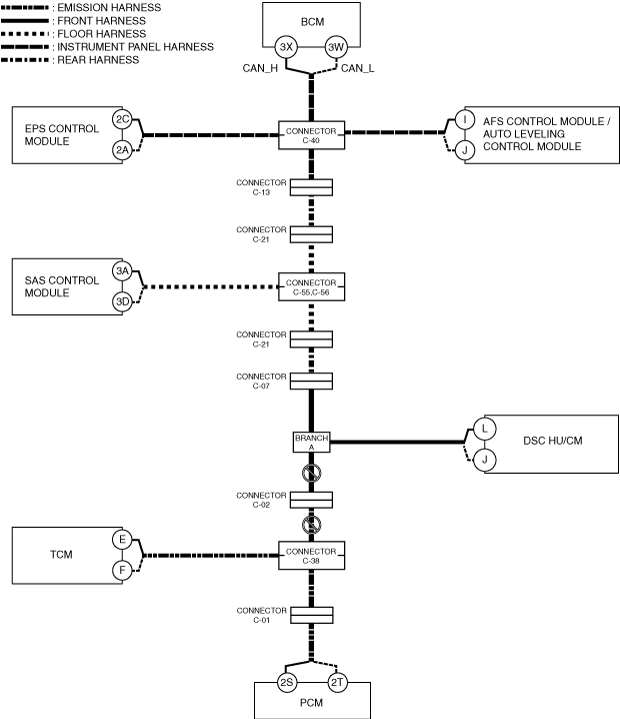
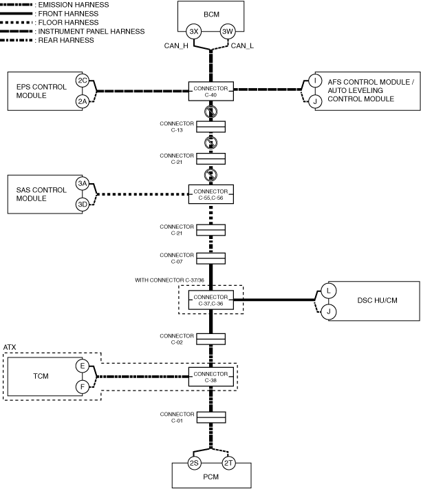
MTX (without connectors C-37, C-36)
-
Possible cause
-
• Connector terminal disconnection, poor contact, damage, deformation, corrosion• PCM power supply voltage or body ground malfunction• Open circuit in wiring harness between PCM and connector C-01• Open circuit in wiring harness between connector C-01 and connector C-02• Open circuit in wiring harness between connector C-02 and branch A• Connector C-01 malfunction• Connector C-02 malfunction• PCM malfunction
System wiring diagram
am3zzw00027586
|
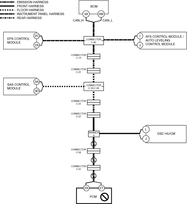
-
Inspection item
-
• PCM power supply voltage-related wiring harness and fuse• PCM body ground related wiring harness• PCM connector• Connector C-01• Connector C-02• Wiring harness between PCM terminal 2S and connector C-01• Wiring harness between PCM terminal 2T and connector C-01• Wiring harness between connector C-01 and connector C-02• Wiring harness between connector C-02 and branch A• PCM
B
Possible cause
-
• Connector terminal disconnection, poor contact, damage, deformation, corrosion• TCM power supply voltage or body ground malfunction• Open circuit in wiring harness between TCM and connector C-38• Connector C-38 malfunction• TCM malfunction
System wiring diagram
am3zzw00027587
|
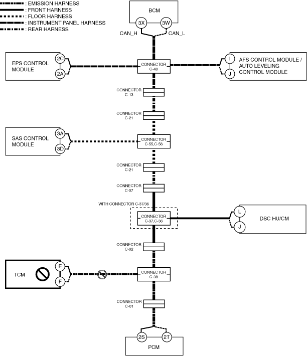
Inspection item
-
• TCM power supply voltage-related wiring harness and fuse• TCM body ground related wiring harness• TCM connector• Connector C-38• Wiring harness between TCM terminal E and connector C-38• Wiring harness between TCM terminal F and connector C-38• TCM
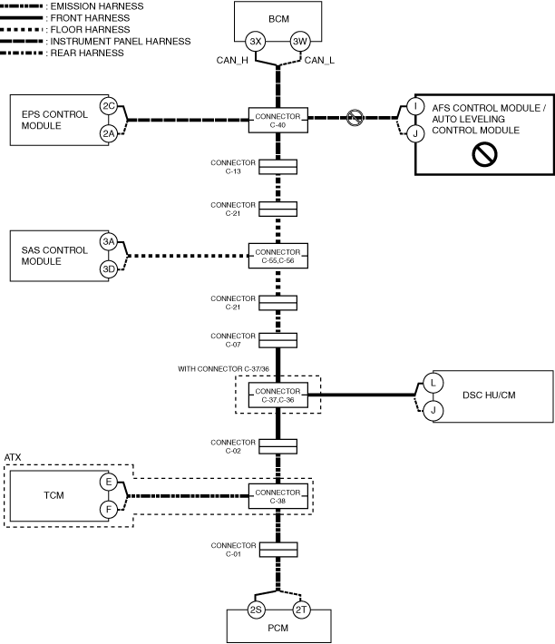
C
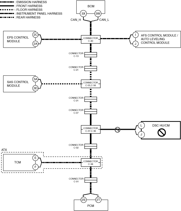
With connectors C-37, C-36
-
Possible cause
-
• Connector terminal disconnection, poor contact, damage, deformation, corrosion• Open circuit in wiring harness between connector C-38 and connector C-02• Open circuit in wiring harness between connector C-02 and connectors C-37,C-36• Connector C-38 malfunction• Connector C-02 malfunction• Connectors C-37, C-36 malfunction
System wiring diagram
am3zzw00027588
|
-
Inspection item
-
• Wiring harness between connector C-38 and connector C-02• Wiring harness between connector C-02 and connectors C-37, C-36• Connector C-38• Connector C-02• Connectors C-37, C-36
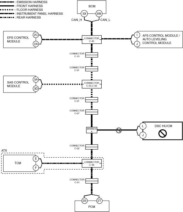
without connectors C-37, C-36
-
Possible cause
-
• Connector terminal disconnection, poor contact, damage, deformation, corrosion• Open circuit in wiring harness between connector C-38 and connector C-02• Open circuit in wiring harness between connector C-02 and branch A• Connector C-38 malfunction• Connector C-02 malfunction
System wiring diagram
am3zzw00027589
|
-
Inspection item
-
• Wiring harness between connector C-38 and connector C-02• Wiring harness between connector C-02 and branch A• Connector C-38• Connector C-02
D
With connectors C-37, C-36
-
Possible cause
-
• Connector terminal disconnection, poor contact, damage, deformation, corrosion• DSC HU/CM power supply voltage or body ground malfunction• Open circuit in wiring harness between DSC HU/CM and connectors C-37, C-36• Connectors C-37, C-36 malfunction• DSC HU/CM malfunction
System wiring diagram
am3zzw00027590
|
-
Inspection item
-
• DSC HU/CM power supply voltage-related wiring harness and fuse• DSC HU/CM body ground related wiring harness• DSC HU/CM connector• Connectors C-37, C-36• Wiring harness between DSC HU/CM terminal L and connectors C-37, C-36• Wiring harness between DSC HU/CM terminal J and connectors C-37, C-36• DSC HU/CM
Without connectors C-37, C-36
-
Possible cause
-
• Connector terminal disconnection, poor contact, damage, deformation, corrosion• DSC HU/CM power supply voltage or body ground malfunction• Open circuit in wiring harness between DSC HU/CM and branch A• DSC HU/CM malfunction
System wiring diagram
am3zzw00027591
|
-
Inspection item
-
• DSC HU/CM power supply voltage-related wiring harness and fuse• DSC HU/CM body ground related wiring harness• DSC HU/CM connector• Wiring harness between DSC HU/CM terminal L and branch A• Wiring harness between DSC HU/CM terminal J and branch A• DSC HU/CM
E
With connectors C-37, C-36
-
Possible cause
-
• Connector terminal disconnection, poor contact, damage, deformation, corrosion• Open circuit in wiring harness between connectors C-55, C-56 and connector C-21• Open circuit in wiring harness between connector C-21 and connector C-07• Open circuit in wiring harness between connector C-07 and connectors C-37, C-36• Connectors C-55, C-56 malfunction• Connector C-21 malfunction• Connector C-07 malfunction• Connectors C-37, C-36 malfunction
System wiring diagram
am3zzw00027592
|
-
Inspection item
-
• Wiring harness between connectors C-55, C-56 and connector C-21• Wiring harness between connector C-21 and connector C-07• Wiring harness between connector C-07 and connectors C-37, C-36• Connectors C-55, C-56• Connector C-07• Connector C-21• Connectors C-37, C-36
Without connectors C-37, C-36
-
Possible cause
-
• Connector terminal disconnection, poor contact, damage, deformation, corrosion• Open circuit in wiring harness between connectors C-55, C-56 and connector C-21• Open circuit in wiring harness between connector C-21 and connector C-07• Open circuit in wiring harness between connector C-07 and branch A• Connectors C-55, C-56 malfunction• Connector C-21 malfunction• Connector C-07 malfunction
System wiring diagram
am3zzw00027593
|

-
Inspection item
-
• Wiring harness between connectors C-55, C-56 and connector C-21• Wiring harness between connector C-21 and connector C-07• Wiring harness between connector C-21 and branch A• Connectors C-55, C-56• Connector C-07• Connector C-21
F
Possible cause
-
• Connector terminal disconnection, poor contact, damage, deformation, corrosion• SAS control module power supply voltage or body ground malfunction• Open circuit in wiring harness between SAS control module and connectors C-55, C-56• Connectors C-55, C-56 malfunction• SAS control module malfunction
System wiring diagram
am3zzw00027594
|
Inspection item
-
• SAS control module power supply voltage-related wiring harness and fuse• SAS control module body ground related wiring harness• SAS control module connector• Connectors C-55, C-56• Wiring harness between SAS control module terminal 3A and connectors C-55, C-56• Wiring harness between SAS control module terminal 3D and connectors C-55, C-56• SAS control module
G
Possible cause
-
• Connector terminal disconnection, poor contact, damage, deformation, corrosion• Open circuit in wiring harness between connector C-40 and connector C-13• Open circuit in wiring harness between connector C-13 and connector C-21• Open circuit in wiring harness between connector C-21 and connectors C-55, C-56• Connector C-40 malfunction• Connector C-13 malfunction• Connector C-21 malfunction• Connectors C-55, C-56 malfunction
System wiring diagram
am3zzw00027595
|
Inspection item
-
• Connector C-40• Connector C-13• Connector C-21• Connectors C-55,C-56• Wiring harness between connector C-40 and connector C-13• Wiring harness between connector C-13 and connector C-21• Wiring harness between connector C-21 and connectors C-55,C-56
H
Possible cause
-
• Connector terminal disconnection, poor contact, damage, deformation, corrosion• AFS control module / auto leveling control module power supply voltage or body ground malfunction• Open circuit in wiring harness between AFS control module / auto leveling control module and connector C-40• Connector C-40 malfunction• AFS control module / auto leveling control module malfunction
System wiring diagram
am3zzw00027596
|
Inspection item
-
• AFS control module / auto leveling control module power supply voltage-related wiring harness and fuse• AFS control module / auto leveling control module body ground related wiring harness• AFS control module / auto leveling control module connector• Connector C-40• Wiring harness between AFS control module / auto leveling control module terminal I and connector C-40• Wiring harness between AFS control module / auto leveling control module terminal J and connector C-40• AFS control module / auto leveling control module
I
Possible cause
-
• Connector terminal disconnection, poor contact, damage, deformation, corrosion• EPS control module power supply voltage or body ground malfunction• Open circuit in wiring harness between EPS control module and connector C-40• Connector C-40 malfunction• EPS control module malfunction
System wiring diagram
am3zzw00027597
|
Inspection item
-
• EPS control module power supply voltage-related wiring harness and fuse• EPS control module body ground related wiring harness• EPS control module connector• Connector C-40• Wiring harness between EPS control module terminal 2C and connector C-40• Wiring harness between EPS control module terminal 2A and connector C-40• EPS control module
J
Possible cause
-
• Connector terminal disconnection, poor contact, damage, deformation, corrosion• Body control module (BCM) power supply voltage or body ground malfunction• Open circuit in wiring harness between body control module (BCM) and connector C-40• Connector C-40 malfunction• Body control module (BCM) malfunction
System wiring diagram
am3zzw00027598
|
Inspection item
-
• Body control module (BCM) power supply voltage-related wiring harness and fuse• Body control module (BCM) body ground related wiring harness• Body control module (BCM) connector• Connector C-40• Wiring harness between body control module (BCM) terminal 3X and connector C-40• Wiring harness between body control module (BCM) terminal 3W and connector C-40• Body control module (BCM)