POWER WINDOW MAIN SWITCH INSPECTION [(US)]
POWER WINDOW MAIN SWITCH INSPECTION [(US)]
SM2566398
id0912000021x1
-
Note
-
• The power outer mirror switch is built into the power window main switch.
Power Window Main Switch Inspection
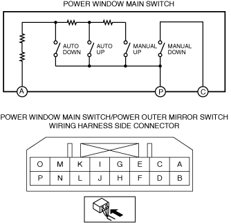
Front side switch (LF)
1.Disconnect the negative battery terminal.
2.Remove the power window main switch. (See POWER WINDOW MAIN SWITCH REMOVAL/INSTALLATION)
3.Verify that the resistance between power window main switch terminals F and P is as indicated in the table.
am3zzw00029970
|

|
Switch Position |
Resistance (ohm) |
Terminal |
|---|---|---|
|
Auto Down
|
297.0—303.0
|
F—P
|
|
Manual Down
|
445.5—454.5
|
|
|
Auto Up
|
683.1—696.9
|
|
|
Manual Up
|
1069.2—1090.8
|
-
• If not as indicated in the table, replace the power window main switch. (See POWER WINDOW MAIN SWITCH REMOVAL/INSTALLATION.)
Front side switch (RF)
1.Disconnect the negative battery terminal.
2.Remove the power window main switch. (See POWER WINDOW MAIN SWITCH REMOVAL/INSTALLATION.)
3.Verify that the resistance between power window main switch terminals A and P is as indicated in the table.
am3zzw00035082
|
|
Switch Position |
Resistance (ohm) |
Terminal |
|---|---|---|
|
Auto Down
|
445.5—454.5
|
A—P
|
|
Auto Up
|
683.1—696.9
|
|
|
Manual Up
|
1069.2—1090.8
|
-
• If not as indicated in the table, replace the power window main switch. (See POWER WINDOW MAIN SWITCH REMOVAL/INSTALLATION.)
4.Verify that the continuity between the power window main switch terminals C and P is as indicated in the table.
|
Switch Position |
Continuity Terminal |
|---|---|
|
Manual Down
|
C—P
|
-
• If not as indicated in the table, replace the power window main switch. (See POWER WINDOW MAIN SWITCH REMOVAL/INSTALLATION.)
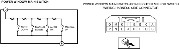
Rear side switch (LR)
1.Disconnect the negative battery terminal.
2.Remove the power window main switch. (See POWER WINDOW MAIN SWITCH REMOVAL/INSTALLATION.)
3.Verify that the resistance between power window main switch terminals D and P is as indicated in the table.
am3zzw00029971
|
|
Switch Position |
Resistance (ohm) |
Terminal |
|---|---|---|
|
Auto Down
|
297.0—303.0
|
D—P
|
|
Manual Down
|
445.5—454.5
|
|
|
Auto Up
|
683.1—696.9
|
|
|
Manual Up
|
1069.2—1090.8
|
-
• If not as indicated in the table, replace the power window main switch. (See POWER WINDOW MAIN SWITCH REMOVAL/INSTALLATION.)
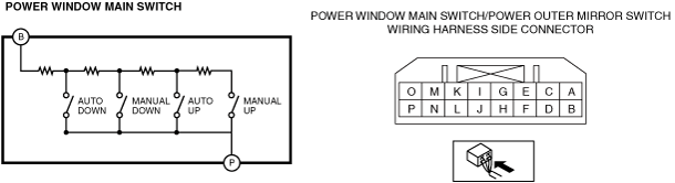
Rear side switch (RR)
1.Disconnect the negative battery terminal.
2.Remove the power window main switch. (See POWER WINDOW MAIN SWITCH REMOVAL/INSTALLATION.)
3.Verify that the resistance between power window main switch terminals B and P is as indicated in the table.
am3zzw00029972
|
|
Switch Position |
Resistance (ohm) |
Terminal |
|---|---|---|
|
Auto Down
|
297.0—303.0
|
B—P
|
|
Manual Down
|
445.5—454.5
|
|
|
Auto Up
|
683.1—696.9
|
|
|
Manual Up
|
1069.2—1090.8
|
-
• If not as indicated in the table, replace the power window main switch. (See POWER WINDOW MAIN SWITCH REMOVAL/INSTALLATION.)
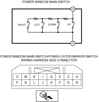
Power Outer Mirror Switch Inspection
Up-down/left-right adjustment switch
1.Disconnect the negative battery terminal.
2.Remove the power window main switch. (See POWER WINDOW MAIN SWITCH REMOVAL/INSTALLATION.)
3.Verify that the resistance between power window main switch terminals H and P is as indicated in the table.
am3zzw00027405
|
|
Switch Position |
Resistance (ohm) |
Terminal |
|---|---|---|
|
Up
|
0
|
H—P
|
|
Down
|
326.7—333.3
|
|
|
Left
|
999.9—1020.1
|
|
|
Right
|
2979.9—3040.1
|
-
• If not as indicated in the table, replace the power window main switch. (See POWER WINDOW MAIN SWITCH REMOVAL/INSTALLATION.)
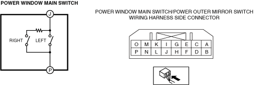
Left/right selection switch
1.Disconnect the negative battery terminal.
2.Remove the power window main switch. (See POWER WINDOW MAIN SWITCH REMOVAL/INSTALLATION.)
3.Verify that the resistance between power window main switch terminals J and P is as indicated in the table.
am3zzw00029969
|
|
Switch Position |
Resistance (ohm) |
Terminal |
|---|---|---|
|
Left
|
0
|
J—P
|
|
Right
|
2090—2310
|
-
• If not as indicated in the table, replace the power window main switch. (See POWER WINDOW MAIN SWITCH REMOVAL/INSTALLATION.)
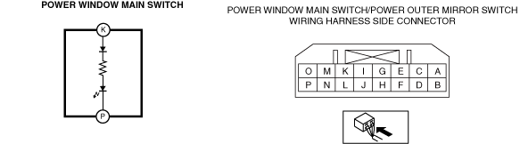
Power Window Switch Illumination Inspection
1.Disconnect the negative battery terminal.
2.Remove the power window main switch. (See POWER WINDOW MAIN SWITCH REMOVAL/INSTALLATION.)
3.Apply battery positive voltage and connect the ground to the rear map light terminals as indicated in the table
am3zzw00029974
|
|
B+ Terminal |
Ground Terminal |
Operation |
|---|---|---|
|
K
|
P
|
LED Turn On
|
4.Verify that the LED is turned on.
-
• If the LED does not turn on, replace the power window main switch. (See POWER WINDOW MAIN SWITCH REMOVAL/INSTALLATION.)