REAR DIFFERENTIAL ASSEMBLY
REAR DIFFERENTIAL ASSEMBLY
SM2515141
id031400146600
Special Service Tool (SST)
|
49 B032 335A
Oil seal installer
|
 |
49 D028 203
Support block
|
 |
49 F027 007
Attachment ø 72
|
 |
|
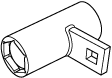
49 F401 331
Bearing installer body
|
 |
49 G030 338
Attachment E
|
 |
49 JP01 002
Holder side bearing
|
 |
|
49 L025 002
Bearing installer
|
 |
49 L027 006
Serrate socket
|
 |
49 L027 007
Hex socket
|
 |
|
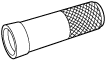
49 M005 797
Oil seal installer
|
 |
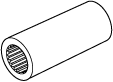
49 V001 525
Bearing installer
|
 |
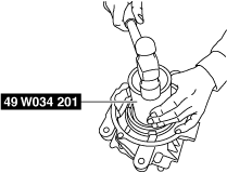
49 W034 201
Dust boot installer
|
 |
Replacement Part
|
Bearing outer race
Quantity: 2
Location of use: Bearing
|
Spacer
Quantity: 1
Location of use: Drive pinion
|
Collapsible spacer
Quantity: 1
Location of use: Drive pinion
|
|
Locknut
Quantity: 1
Location of use: Drive pinion
|
Oil seal (side gear)
Quantity: 2
Location of use: Side gear
|
Oil seal (Coupling component)
Quantity: 1
Location of use: Coupling component
|
Oil and Chemical Type
|
Rear differential oil
Type: MAZDA LONG LIFE HYPOID GEAR OIL SG1
|
Sealant
Type: TB1217C or equivalent
|
-
Warning
-
• The engine stand is equipped with a self-lock mechanism, however, if the rear differential is in a tilted condition, the self-lock mechanism could become inoperative. If the rear differential unexpectedly rotates it could cause injury, therefore do not maintain the rear differential in a tilted condition. When turning the rear differential, grasp the rotation handle firmly.
-
Caution
-
• Clean away the old sealant before applying the new sealant.• Install the rear cover before the applied sealant starts to harden.• Allow the sealant to set at least 30 minutes after installation before filling the differential with the specified oil.
1.Disassemble in the order shown in the figure.
am3zzw00031638
|

|
1
|
Gear case
|
|
2
|
Side bearing
(See Side Bearing Assembly Note.)
|
|
3
|
Thrust washer
(See Thrust washer Assembly Note.)
|
|
4
|
Side gear
|
|
5
|
Thrust washer
|
|
6
|
Pinion gear
|
|
7
|
Pinion shaft
|
|
8
|
Pin
|
|
9
|
Ring gear
(See Ring Gear Assembly Note.)
|
|
10
|
Differential carrier
|
|
11
|
Bearing outer race
|
|
12
|
Spacer
|
|
13
|
Bearing inner race (rear)
|
|
14
|
Bearing inner race (front)
|
|
15
|
Collapsible spacer
|
|
16
|
Drive pinion
|
|
17
|
Locknut
(See Locknut Assembly Note.)
|
|
18
|
Adjusting shim (LH)
(See Adjusting Shim Assembly Note.)
|
|
19
|
Spacer
|
|
20
|
Rear differential component
|
|
21
|
Adjusting shim (RH)
(See Adjusting Shim Assembly Note.)
|
|
22
|
Rear cover
(See Rear Cover Assembly Note.)
|
|
23
|
Differential oil temperature sensor
|
|
24
|
Oil seal (Side gear)
|
|
25
|
Oil seal (Coupling component)
|
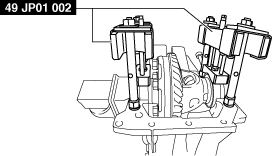
Side Bearing Assembly Note
-
Caution
-
• Do not mix up the left and right side bearing inner races.
1.Press the side bearing inner races into the gear case using the SSTs.
ac5jjw00010900
|
Thrust washer Assembly Note
1.Assemble the side gears, thrust washers and pinion gears to the gear case, then assemble the knock pin.
2.After assembling the knock pin, make a crimp so that the pin will not come out of the gear case.
3.Set a dial gauge to the pinion gear as indicated in the figure.
am3zzw00031639
|
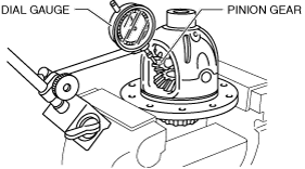
4.Secure one of the side gears.
5.Move the pinion gear and measure the backlash at the end of the pinion gear.
-
• If the backlash exceeds the standard, use the thrust washers to adjust.
-
Rear differential backlash of pinion gear and side gear
-
0.1 mm {0.004 in} or less
Thrust washer thickness
|
Identification mark |
Thickness |
|---|---|
|
9
|
0.90 mm {0.035 in}
|
|
95
|
0.95 mm {0.037 in}
|
|
0
|
1.00 mm {0.0394 in}
|
|
05
|
1.05 mm {0.0413 in}
|
|
1
|
1.10 mm {0.0433 in}
|
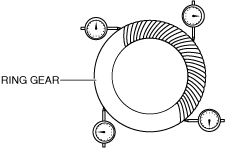
Ring Gear Assembly Note
1.Align the marks placed on the ring gear case at the time of disassembly and tighten the bolts in diagonal order.
am3zzw00031640
|

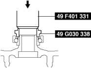
Bearing Outer Race Assembly Note
1.Press in the bearing outer race using the SSTs and a press.
am3zzw00031641
|

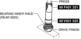
Spacer, Bearing Inner Race Assembly Note
1.Install a new spacer of the same size as the originally installed spacer.
Spacer thickness
|
Identification mark |
Thickness (mm {IN}) |
Identification mark |
Thickness (mm {IN}) |
|---|---|---|---|
|
08
|
3.08 {0.1213}
|
29
|
3.29 {0.1295}
|
|
09
|
3.095 {0.1219}
|
30
|
3.305 {0.1301}
|
|
11
|
3.11 {0.1224}
|
32
|
3.32 {0.1307}
|
|
12
|
3.125 {0.1230}
|
33
|
3.335 {0.1313}
|
|
14
|
3.14 {0.1236}
|
35
|
3.35 {0.1319}
|
|
15
|
3.155 {0.1242}
|
36
|
3.365 {0.1325}
|
|
17
|
3.17 {0.1248}
|
38
|
3.38 {0.1331}
|
|
18
|
3.185 {0.1254}
|
39
|
3.395 {0.1337}
|
|
20
|
3.20 {0.1260}
|
41
|
3.41 {0.1343}
|
|
21
|
3.215 {0.1266}
|
42
|
3.425 {0.1348}
|
|
23
|
3.23 {0.1272}
|
44
|
3.44 {0.1354}
|
|
24
|
3.245 {0.1278}
|
45
|
3.455 {0.1360}
|
|
26
|
3.26 {0.1283}
|
47
|
3.47 {0.1366}
|
|
27
|
3.275 {0.1289}
|
—
|
—
|
2.Press the bearing inner race (rear bearing) into the drive pinion using the SSTs and a press.
am3zzw00031642
|
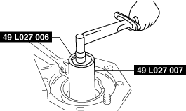
Locknut Assembly Note
Drive pinion preload adjustment
1.Apply differential oil to a new locknut.
2.Assemble a new collapsible spacer, bearing inner race (front bearing), spacer and locknut to the drive pinion, and temporarily tighten the locknut.
3.Turn the serrated part of the drive pinion by hand to seat the bearing.
4.Tighten the locknut temporarily tightened in Step 1 from the lower limit of the specified tightening torque using the SSTs, and make this the specified preload.
aaxjjw00008286
|
-
• If the specified preload cannot be obtained within the specified tightening torque, replace the collapsible spacer and inspect again.
-
Rear differential drive pinion preload
-
0.20—0.48 N·m {2.1—4.8 kgf·cm, 1.8—4.2 in·lbf}
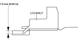
5.Crimp the locknut using a chisel and hammer.
am3zzw00031643
|
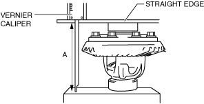
Adjusting Shim Assembly Note
1.Assemble the differential carrier to the SSTs.
2.Assemble the spacer to the differential carrier.
3.Using a vernier caliper and straight edge, measure the height of the rear differential component. This is dimension A.
am3zzw00031644
|
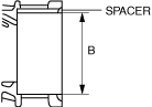
4.Measure the width of the installed differential in the differential carrier with the spacer installed. This is value B.
am3zzw00031645
|
5.The combined thickness of the left and right adjusting shims is obtained by the following formula.
C1 = B – A + 0.110 mm {0.00433 in} C2 = B – A + 0.200 mm {0.00787 in}
6.If the combined thickness of the previously installed adjusting shims is between C1 and C2, use the shims as they are.
7.If the combined thickness of the previously installed adjusting shims is not between C1 and C2, or if the adjusting shims have to be replaced, select two appropriate adjusting shims from the table below.
Adjusting shim thickness
|
Identification mark |
Thickness (mm {IN}) |
Identification mark |
Thickness (mm {IN}) |
|---|---|---|---|
|
339
|
3.39 {0.133}
|
393
|
3.93 {0.155}
|
|
342
|
3.42 {0.135}
|
396
|
3.96 {0.156}
|
|
345
|
3.45 {0.136}
|
399
|
3.99 {0.157}
|
|
348
|
3.48 {0.13}
|
402
|
4.02 {0.158}
|
|
351
|
3.51 {0.138}
|
405
|
4.05 {0.159}
|
|
354
|
3.54 {0.139}
|
408
|
4.08 {0.161}
|
|
357
|
3.57 {0.141}
|
411
|
4.11 {0.162}
|
|
360
|
3.60 {0.142}
|
414
|
4.14 {0.163}
|
|
363
|
3.63 {0.143}
|
417
|
4.17 {0.164}
|
|
366
|
3.66 {0.144}
|
420
|
4.20 {0.165}
|
|
369
|
3.69 {0.145}
|
423
|
4.23 {0.167}
|
|
372
|
3.72 {0.146}
|
426
|
4.26 {0.168}
|
|
375
|
3.75 {0.148}
|
429
|
4.29 {0.169}
|
|
378
|
3.78 {0.149}
|
432
|
4.32 {0.170}
|
|
381
|
3.81 {0.150}
|
435
|
4.35 {0.171}
|
|
384
|
3.84 {0.151}
|
438
|
4.38 {0.172}
|
|
387
|
3.87 {0.152}
|
441
|
4.41 {0.174}
|
|
390
|
3.90 {0.154}
|
—
|
—
|
-
Caution
-
• If adjusting shims are to be reused, do not mix up the left and right shims.• Do not mix up the left and right side bearing outer races and spacers.
8.Assemble the rear differential component to the differential carrier.
9.Tap the selected adjusting shim between the spacer and the bearing race with a plastic hammer.
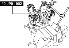
10.Perform the ring gear and drive pinion backlash adjustment.
-
Note
-
• Install the SST so that it does not contact the ring gear.
 ac5jjw00010902
- (1)Install the SST and dial gauge to the differential carrier using a vise as shown in the figure.
-
ac5jjw00010903
-
SST tightening torque
-
5.0 N·m {51 kgf·cm, 44 in·lbf}
-
Note
-
• Measure the backlash at 4 locations around the ring gear. Make sure that 1 of the 4 locations is within the standard, and the minimum value for the 4 locations is 0.05 mm in or more and the variance is 0.07 mm or less.am3zzw00031646
-
- (2)Secure the drive pinion and measure the backlash from when the ring gear is moved.
-
-
Drive pinion and ring gear backlash
-
Standard: 0.09—0.14 mm {0.004—0.005 in}Minimum: 0.05 mm {0.002 in} or moreVariance: 0.07 mm {0.003 in} or less
-
• If the backlash is not within the specification, adjust the gear case component by moving it in the axial direction.
-
Note
-
• When moving the gear case component in the axial direction, replace the adjusting shims. If the adjusting shim on the right side is replaced with one that is 0.03 mm {0.001 in} thicker, replace the one on the left with one that is 0.03 mm {0.001 in} thinner.
-
Adjusting shim thickness
Identification mark
Thickness (mm {IN})
Identification mark
Thickness (mm {IN})
3393.39 {0.133}3933.93 {0.155}3423.42 {0.135}3963.96 {0.156}3453.45 {0.136}3993.99 {0.157}3483.48 {0.13}4024.02 {0.158}3513.51 {0.138}4054.05 {0.159}3543.54 {0.139}4084.08 {0.161}3573.57 {0.141}4114.11 {0.162}3603.60 {0.142}4144.14 {0.163}3633.63 {0.143}4174.17 {0.164}3663.66 {0.144}4204.20 {0.165}3693.69 {0.145}4234.23 {0.167}3723.72 {0.146}4264.26 {0.168}3753.75 {0.148}4294.29 {0.169}3783.78 {0.149}4324.32 {0.170}3813.81 {0.150}4354.35 {0.171}3843.84 {0.151}4384.38 {0.172}3873.87 {0.152}4414.41 {0.174}3903.90 {0.154}—— -
11.Inspect the drive pinion and ring gear teeth contact points.
- (1)Coat both surfaces of the ring gear uniformly with a thin red lead coating.
- (2)While rotating the ring gear back and forth by hand, rotate the drive pinion several times and inspect the tooth contact.
- (3)Inspect the tooth contacts in four locations around the ring gear, and check that the tooth contacts showing the red lead coating are the same as the pattern indicated in the figure.
-
-
• If the tooth contact is good, wipe off the red lead coating.• If it is not good, adjust the pinion height, then adjust the backlash.ac5jjw00011360
-
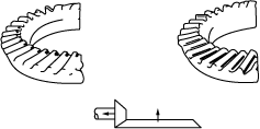
― If toe and flank contact appears as shown in the figure, replace the spacer with a thinner one, and move the drive pinion outward.aaxjjw00008294
-
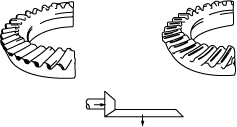
― If heel and face contact appears as indicated in the figure, replace the spacer with a thicker one and move the drive the pinion inward.aaxjjw00008295
-
Spacer thickness
Identification mark
Thickness (mm {IN})
Identification mark
Thickness (mm {IN})
083.08 {0.1213}293.29 {0.1295}093.095 {0.1219}303.305 {0.1301}113.11 {0.1224}323.32 {0.1307}123.125 {0.1230}333.335 {0.1313}143.14 {0.1236}353.35 {0.1319}153.155 {0.1242}363.365 {0.1325}173.17 {0.1248}383.38 {0.1331}183.185 {0.1254}393.395 {0.1337}203.20 {0.1260}413.41 {0.1343}213.215 {0.1266}423.425 {0.1348}233.23 {0.1272}443.44 {0.1354}243.245 {0.1278}453.455 {0.1360}263.26 {0.1283}473.47 {0.1366}273.275 {0.1289}—— -
Oil Seal (Side gear) Assembly Note
1.Apply differential oil to the new oil seal lip.
2.Assemble the oil seal using the SSTs.
ac5jjw00003284
|
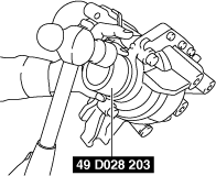
Oil Seal (Coupling component) Assembly Note
1.Apply differential oil to the new oil seal lip.
2.Assemble the oil seal using the SSTs.
ac5jjw00003285
|
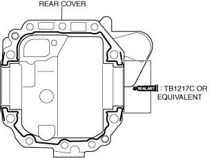
Rear Cover Assembly Note
1.Clean the alignment surface of the carrier and rear cove.
2.Apply a thin layer of silicone sealant TB1217C or equivalent to the contact surfaces of the rear cover.
am3zzw00035219
|
3.Apply pressure to the case using a press and install the rear cover using the SSTs (49 B032 335A) as shown in the figure.
am3zzw00031648
|
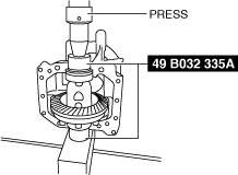
-
Caution
-
• Do not apply pressure of 2 t or more.
4.Install the bolts with the specified torque as shown in the figure.
am3zzw00031649
|
