REAR DRIVE SHAFT DISASSEMBLY/ASSEMBLY
REAR DRIVE SHAFT DISASSEMBLY/ASSEMBLY
SM2515138
id031300145100
Replacement Part
|
Boot band (differential side)
Quantity: 2
Location of use: Boot (differential side)
|
Snap ring
Quantity: 1
Location of use: Double offset joint
|
Boot (differential side)
Quantity: 1
Location of use: Rear drive shaft (differential side)
|
|
Boot band (wheel side)
Quantity: 2
Location of use: Boot (wheel side)
|
Boot (wheel side)
Quantity: 1
Location of use: Rear drive shaft (wheel side)
|
—
|
Oil and Chemical Type
|
Grease
Type: Maintenance parts
|
-
Caution
-
• Do not allow a magnetized tool such as a magnetized screwdriver to come into contact with the ABS sensor rotor. If the ABS sensor rotor becomes magnetized it will be unable to read the ABS wheel speed sensor waveform correctly resulting in an ABS system malfunction to be determined and the inability to perform ABS control. If a magnetized object comes into contact with the ABS sensor rotor, it will be necessary to newly replace the rear drive shaft (ABS sensor rotor).
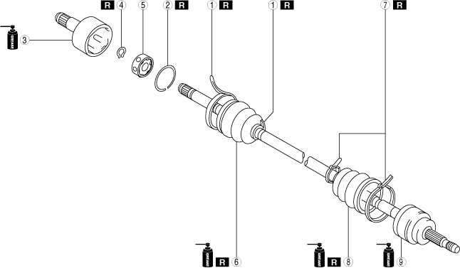
1.Disassemble in the order shown in the figure.
2.Assemble in the reverse order of removal.
ac3jjw00002061
|
|
1
|
Boot band (differential side)
(See Boot Band Disassembly Note.)
(See Boot Band Assembly Note.)
|
|
2
|
Clip
|
|
3
|
Outer ring
|
|
4
|
Snap ring
|
|
5
|
Ball, inner ring, cage
|
|
6
|
Boot (differential side)
|
|
7
|
Boot band (wheel side)
(See Boot Band Disassembly Note.)
(See Boot Band Assembly Note.)
|
|
8
|
Boot (wheel side)
|
|
9
|
Shaft and ball joint component
|
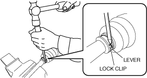
Boot Band Disassembly Note
1.Using a flat chisel and hammer, lightly tap the lever of the boot band to disconnect the lock clip.
am3zzw00031444
|
2.Remove the boot band using pliers.
aaxjjw00013154
|
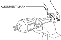
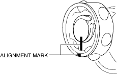
Clip, Outer Ring Disassembly Note
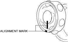
1.Place alignment marks on the shaft and outer ring.
-
Caution
-
• To prevent part damage, do not use a punch or similar tool to place alignment marks. Use paint.
am3zzw00031445
|
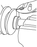
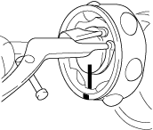
2.Remove the clip using a screwdriver.
atstjw00000061
|
3.Remove the outer ring from the shaft.
4.Wipe off grease on the outer ring using a clean cloth.
Snap ring, Ball, Inner Ring, Cage Disassembly Note
1.Place alignment marks on the shaft, inner ring, and cage.
-
Caution
-
• To prevent part damage, do not use a punch or similar tool to place alignment marks. Use paint.
am3zzw00031446
|
2.Remove the snap ring using snap ring pliers.
atstjw00000063
|
3.Remove the ball, inner ring, and cage from the shaft.
-
Caution
-
• When using a hammer and urethane bar or equivalent, be careful not to damage the ball, ball sliding area, and cage.
-
Note
-
• If the ball, inner ring, and cage cannot be removed from the shaft, lightly tap the inner ring evenly using a hammer and urethane bar or equivalent, and remove the ball, inner ring, and cage from the shaft.
4.Wipe off grease on the shaft, ball, inner ring, and cage using a clean cloth.
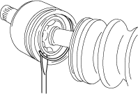
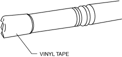
Boot (Differential Side) Disassembly Note
1.Wrap vinyl tape around the spline area of the shaft to prevent damage to the boot.
am3zzw00031447
|
2.Remove the boot (differential side).
3.Wipe off grease on the boot (differential side) using a clean cloth.
Boot (Wheel Side) Disassembly Note
1.Wrap vinyl tape around the spline area of the shaft to prevent damage to the boot.
am3zzw00031447
|
2.Remove the boot (wheel side).
3.Wipe off grease on the boot (wheel side) and ball joint using a clean cloth.
Boot (Wheel Side) Assembly Note
-
Note
-
• The boot shapes on the wheel side and the differential side are different. Do not assemble the wrong boot by mistake.
1.Insert the shaft through the boot (wheel side) with vinyl tape wrapped around the spline area of the shaft.
2.Apply the specified grease to the ball joint and boot (wheel side).
-
Note
-
• Apply the grease from the tube. Do not touch the grease directly with your hand.
-
Grease amount
-
35—55 g {1.3—1.9 oz}
3.Assemble the boot (wheel side) to the ball joint.
Boot (Differential Side) Assembly Note
-
Note
-
• The boot shapes on the wheel side and the differential side are different. Do not assemble the wrong boot by mistake.
1.Insert the shaft through the boot (differential side) with vinyl tape left wrapped around the spline area of the shaft.
2.Remove the vinyl tape left wrapped around the spline area of the shaft.
Ball, Inner Ring, Cage, Snap Ring Assembly Note
1.Assemble the shaft, inner ring, and cage with the alignment marks aligned.
-
Caution
-
• When using the hammer and urethane bar or equivalent, be careful not to damage the ball, ball sliding area, and cage.
-
Note
-
• If the ball, inner ring, and cage cannot be assembled to the shaft, lightly tap the inner ring evenly using a hammer and urethane bar or equivalent, and assemble the ball, inner ring, and cage to shaft.
am3zzw00031448
|
2.Assemble a new snap ring using snap ring pliers.
atstjw00000063
|
3.Verify that the snap ring is assembled correctly in the groove of the shaft.
Outer Ring, Clip Assembly Note
1.Apply the specified grease to the outer ring and boot (differential side).
-
Note
-
• Apply the grease from the tube. Do not touch the grease directly with your hand.
-
Grease amount
-
60—80 g {2.2—2.8 oz}
2.Assemble the outer ring with the alignment marks on the shaft and outer ring aligned.
am3zzw00031445
|
3.Assemble a new clip using a screwdriver.
atstjw00000061
|
4.Verify that the clip is assembled correctly in the groove of the outer ring.
5.Assemble the boot (differential side) to the outer ring.
6.Set the drive shaft length to the standard.
Drive shaft (double offset joint) full length (standard)
|
Full length (standard) |
|
|---|---|
|
LH
|
828.8—838.8 mm {32.63—33.02 in}
|
|
RH
|
869.6—879.6 mm {34.24—34.62 in}
|
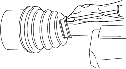
7.Release any trapped air from the boot by carefully lifting up the small end of the boot with a screwdriver wrapped in a clean cloth.
-
Note
-
• Do not damage the boot. Verify that there is no grease leakage.• If the boot is deformed, it may not be possible to perform the full-length adjustment of the shaft.
aatjjw00009777
|
8.Verify that the drive shaft length is within the standard when the inside of the boot is at atmospheric pressure.
-
• If not within the standard, repeat from Step 6.
Boot Band Assembly Note
-
Warning
-
• Your hands could be injured while assembling the boot band. Therefore always wear gloves.
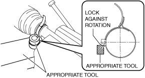
1.Apply rust prevention oil to the inside of the boot band.
2.Lock the boot band against rotation using an appropriate tool as shown in the figure.
am3zzw00031449
|
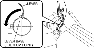
3.Lock the boot band against rotation using an appropriate tool as shown in the figure.
-
Caution
-
• Do not put the boot band back to its original position after bending it using pliers because it will damage the boot band.
am3zzw00031450
|
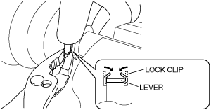
4.Hold the rotated lever with a finger and temporarily secure the lock clip by squeezing it with a pair of pliers.
-
Caution
-
• If the lever flips back by reactive force, press it back again a maximum of only three times to prevent damage to the boot band.
am3zzw00031451
|
5.Lightly tap the lock clip with a hammer until the gap in the lock clip is 1 mm {0.04 in} or less.
am3zzw00031452
|
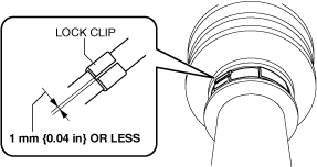
-
• If there is any malfunction, replace with a new part.
6.The gap between the boot band and the boot band lever is 1 mm {0.04 in} or less.
am3zzw00031453
|
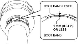
-
• If there is any malfunction, replace with a new part.
7.After assembling the boot band, perform the following verification.
-
• The boot band does not protrude from the band assembly area.• The lever is not deformed.• The boot and boot band are not damaged.• The boot is not damaged.