OPERATION USING STEERING SWITCH NOT POSSIBLE
OPERATION USING STEERING SWITCH NOT POSSIBLE
SM2337309
id160300001300
Outline
|
Possible cause
|
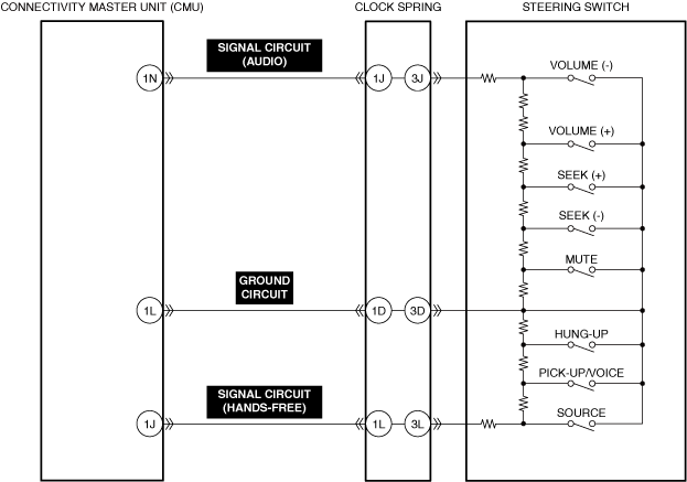
• Connector or terminal malfunction of the following parts:
• Short to power supply, short to ground, or open circuit in steering switch signal circuit
• Steering switch malfunction
• Clock spring malfunction
• Connectivity master unit (CMU) malfunction
|
 |
|
 |
|
 |
|
 |
|
Diagnostic Procedure
|
Step |
Inspection |
Results |
Action |
|---|---|---|---|
|
1
|
VERIFY ALL SYSTEM DTCs
• Perform the DTC inspection. (Refer to the [DTC INSPECTION] in the workshop manual)
• Are any DTCs displayed?
|
Yes
|
Repair the malfunctioning location according to the applicable DTC troubleshooting.
|
|
No
|
Go to the next step.
|
||
|
2
|
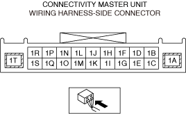
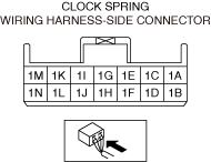
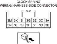
INSPECT STEERING SWITCH, CLOCK SPRING, AND CONNECTIVITY MASTER UNIT (CMU) CONNECTORS FOR MALFUNCTION
• Inspect the applicable connector and terminal. (Refer to the [CONNECTOR INSPECTION] in the workshop manual)
• Are the connector and terminal normal?
|
Yes
|
Go to the next step.
|
|
No
|
Repair or replace the malfunctioning location and perform the repair completion verification.
|
||
|
3
|
INSPECT STEERING SWITCH SIGNAL CIRCUIT FOR SHORT TO POWER SUPPLY, SHORT TO GROUND AND OPEN CIRCUIT
• Inspect the signal circuit for a short to power supply, short to ground, and an open circuit. (Refer to the [CIRCUIT INSPECTION] in the workshop manual)
• Is the circuit normal?
|
Yes
|
Go to the next step.
|
|
No
|
Repair or replace the malfunctioning location and perform the repair completion verification.
|
||
|
4
|
INSPECT STEERING SWITCH FOR MALFUNCTION
• Inspect the applicable part. (Refer to the [STEERING SWITCH INSPECTION] in the workshop manual)
• Is the part normal?
|
Yes
|
Go to the next step.
|
|
No
|
Repair or replace the malfunctioning location and perform the repair completion verification.
(Refer to the [STEERING SWITCH REMOVAL/INSTALLATION] in the workshop manual)
|
||
|
5
|
INSPECT CLOCK SPRING FOR MALFUNCTION
• Inspect the applicable part. (Refer to the [CLOCK SPRING INSPECTION] in the workshop manual)
• Is the part normal?
|
Yes
|
Go to the next step.
|
|
No
|
Repair or replace the malfunctioning location and perform the repair completion verification.
(Refer to the [CLOCK SPRING REMOVAL/INSTALLATION] in the workshop manual)
|
||
|
Repair completion verification
|
VERIFY THAT VEHICLE IS REPAIRED
• Install/connect the part removed/disconnected during the troubleshooting procedure.
• Has the malfunction symptom been eliminated?
|
Yes
|
Complete the symptom troubleshooting. (Explain contents of repair to customer)
|
|
No
|
Refer to the controller area network (CAN) malfunction diagnosis flow to inspect for a CAN communication error.
(Refer to the [CONTROLLER AREA NETWORK (CAN) MALFUNCTION DIAGNOSIS FLOW] in the workshop manual)
If the CAN communication is normal, perform the diagnosis from Step 1.
• If the malfunction is not resolved, replace the connectivity master unit (CMU). (Refer to the [CONNECTIVITY MASTER UNIT (CMU) REMOVAL/INSTALLATION] in the workshop manual)
|