NO SOUND OUTPUT IN ALL MODES
NO SOUND OUTPUT IN ALL MODES
SM2337303
id160300000400
Without Bose®
Outline
|
Possible cause
|
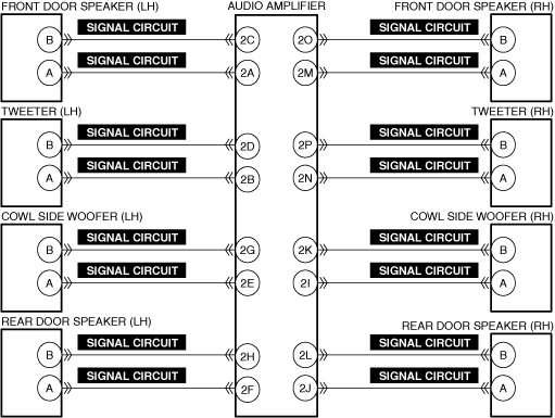
• Connector or terminal malfunction of the following parts:
• Short to ground or open circuit in speaker signal circuit
• Front door speaker malfunction
• Tweeter malfunction
• Cowl side woofer malfunction
• Rear door speaker malfunction
• Audio amplifier malfunction
|
||
 |
|||
 |
 |
 |
|
 |
|||
Diagnostic Procedure
|
Step |
Inspection |
Results |
Action |
|---|---|---|---|
|
1
|
VERIFY ALL SYSTEM DTCs
• Perform the DTC inspection. (Refer to the [DTC INSPECTION] in the workshop manual)
• Are any DTCs displayed?
|
Yes
|
Repair the malfunctioning location according to the applicable DTC troubleshooting.
|
|
No
|
Go to the next step.
|
||
|
2
|
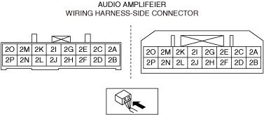
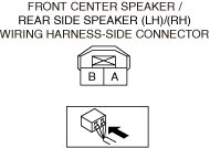
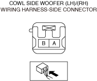
INSPECT SPEAKER AND AUDIO AMPLIFIER CONNECTORS FOR MALFUNCTION
• Inspect the applicable connector and terminal. (Refer to the [CONNECTOR INSPECTION] in the workshop manual)
• Are the connector and terminal normal?
|
Yes
|
Go to the next step.
|
|
No
|
Repair or replace the malfunctioning location and perform the repair completion verification.
|
||
|
3
|
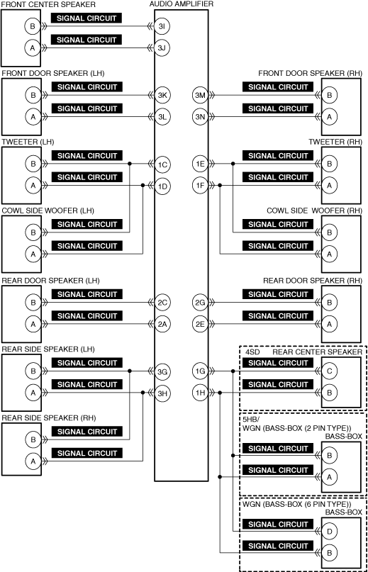
INSPECT SPEAKER SIGNAL CIRCUIT FOR SHORT TO GROUND AND OPEN CIRCUIT
• Inspect the signal circuit for a short to ground and open circuit. (Refer to the [CIRCUIT INSPECTION] in the workshop manual)
• Is the circuit normal?
|
Yes
|
Go to the next step.
|
|
No
|
Repair or replace the malfunctioning location and perform the repair completion verification.
|
||
|
4
|
INSPECT SPEAKER FOR MALFUNCTION
• Inspect the applicable part. (Refer to the [SPEAKER INSPECTION] in the workshop manual)
• Is the part normal?
|
Yes
|
Go to the next step.
|
|
No
|
Repair or replace the malfunctioning location and perform the repair completion verification.
(Refer to the [FRONT DOOR SPEAKER REMOVAL/INSTALLATION] in the workshop manual)
(Refer to the [TWEETER REMOVAL/INSTALLATION] in the workshop manual)
(Refer to the [COWL SIDE WOOFER REMOVAL/INSTALLATION] in the workshop manual)
(Refer to the [REAR DOOR SPEAKER REMOVAL/INSTALLATION] in the workshop manual)
|
||
|
Repair completion verification
|
VERIFY THAT VEHICLE IS REPAIRED
• Install/connect the part removed/disconnected during the troubleshooting procedure.
• Has the malfunction symptom been eliminated?
|
Yes
|
Complete the symptom troubleshooting. (Explain contents of repair to customer)
|
|
No
|
Refer to the controller area network (CAN) malfunction diagnosis flow to inspect for a CAN communication error.
(Refer to the [CONTROLLER AREA NETWORK (CAN) MALFUNCTION DIAGNOSIS FLOW] in the workshop manual)
If the CAN communication is normal, perform the diagnosis from Step 1.
• If the malfunction is not resolved, replace the audio amplifier. (Refer to the [AUDIO AMPLIFIER REMOVAL/INSTALLATION] in the workshop manual)
|
With Bose®
Outline
|
Possible cause
|
• Connector or terminal malfunction of the following parts:
• Short to ground or open circuit in speaker signal circuit
• Front center speaker malfunction
• Front door speaker malfunction
• Tweeter malfunction
• Cowl side woofer malfunction
• Rear door speaker malfunction
• Rear side speaker malfunction
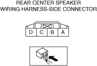
• Rear center speaker malfunction (4SD)
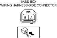
• Bass-box malfunction (5HB/WGN)
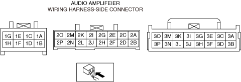
• Audio amplifier malfunction
|
||
 |
|||
 |
|
|
|
 |
 |
 |
|
 |
|||
Diagnostic Procedure
|
Step |
Inspection |
Results |
Action |
|---|---|---|---|
|
1
|
VERIFY ALL SYSTEM DTCs
• Perform the DTC inspection. (Refer to the [DTC INSPECTION] in the workshop manual)
• Are any DTCs displayed?
|
Yes
|
Repair the malfunctioning location according to the applicable DTC troubleshooting.
|
|
No
|
Go to the next step.
|
||
|
2
|
INSPECT SPEAKER AND AUDIO AMPLIFIER CONNECTORS FOR MALFUNCTION
• Inspect the applicable connector and terminal. (Refer to the [CONNECTOR INSPECTION] in the workshop manual)
• Are the connector and terminal normal?
|
Yes
|
Go to the next step.
|
|
No
|
Repair or replace the malfunctioning location and perform the repair completion verification.
|
||
|
3
|
INSPECT SPEAKER SIGNAL CIRCUIT FOR SHORT TO GROUND AND OPEN CIRCUIT
• Inspect the signal circuit for a short to ground and open circuit. (Refer to the [CIRCUIT INSPECTION] in the workshop manual)
• Is the circuit normal?
|
Yes
|
Go to the next step.
|
|
No
|
Repair or replace the malfunctioning location and perform the repair completion verification.
|
||
|
4
|
INSPECT SPEAKER FOR MALFUNCTION
• Inspect the applicable part. (Refer to the [SPEAKER INSPECTION] in the workshop manual)
• Is the part normal?
|
Yes
|
Go to the next step.
|
|
No
|
Repair or replace the malfunctioning location and perform the repair completion verification.
(Refer to the [FRONT CENTER SPEAKER REMOVAL/INSTALLATION] in the workshop manual)
(Refer to the [FRONT DOOR SPEAKER REMOVAL/INSTALLATION] in the workshop manual)
(Refer to the [TWEETER REMOVAL/INSTALLATION] in the workshop manual)
(Refer to the [COWL SIDE WOOFER REMOVAL/INSTALLATION] in the workshop manual)
(Refer to the [REAR DOOR SPEAKER REMOVAL/INSTALLATION] in the workshop manual)
(Refer to the [REAR SPEAKER REMOVAL/INSTALLATION] in the workshop manual)
(Refer to the [BASS-BOX REMOVAL/INSTALLATION] in the workshop manual)
|
||
|
Repair completion verification
|
VERIFY THAT VEHICLE IS REPAIRED
• Install/connect the part removed/disconnected during the troubleshooting procedure.
• Has the malfunction symptom been eliminated?
|
Yes
|
Complete the symptom troubleshooting. (Explain contents of repair to customer)
|
|
No
|
Refer to the controller area network (CAN) malfunction diagnosis flow to inspect for a CAN communication error.
(Refer to the [CONTROLLER AREA NETWORK (CAN) MALFUNCTION DIAGNOSIS FLOW] in the workshop manual)
If the CAN communication is normal, perform the diagnosis from Step 1.
• If the malfunction is not resolved, replace the audio amplifier. (Refer to the [AUDIO AMPLIFIER REMOVAL/INSTALLATION] in the workshop manual)
|