SHROUD PANEL REMOVAL/INSTALLATION [(US)]
SHROUD PANEL REMOVAL/INSTALLATION [(US)]
SM2336330
id0910008019x1
1.Disconnect the negative battery terminal. (See NEGATIVE BATTERY TERMINAL DISCONNECTION/CONNECTION [(US)].)
2.Remove the following parts:
- (1)Upper face (See UPPER FACE REMOVAL/INSTALLATION [(US)].)
- (2)Front bumper (See FRONT BUMPER REMOVAL/INSTALLATION [(US)].)
- (3)Front combination light (See FRONT COMBINATION LIGHT REMOVAL/INSTALLATION.)
- (4)Horn (See HORN REMOVAL/INSTALLATION.)
- (5)Shroud upper member (See SHROUD UPPER MEMBER REMOVAL/INSTALLATION [(US)].)
- (6)Intake air guide (upper) (See INTAKE AIR GUIDE REMOVAL/INSTALLATION.)
- (7)Intake air guide (lower) (See INTAKE AIR GUIDE REMOVAL/INSTALLATION.)
- (8)Front under cover No.1 (See FRONT UNDER COVER No.1 REMOVAL/INSTALLATION.)
-
Caution
-
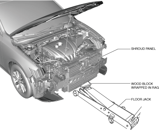
• The front bumper reinforcement supports the shroud panel. After removing the front bumper reinforcement, an excessive load applied to the shroud panel could result in damage. When removing the front bumper reinforcement, always use a floor jack to support the shroud panel.
3.Support the shroud panel using a floor jack.
am3zzw00023227
|
4.Remove the following parts:
- (1)Hood (See HOOD REMOVAL/INSTALLATION.)
- (2)Front bumper reinforcement (See FRONT BUMPER REINFORCEMENT REMOVAL/INSTALLATION.)
- (3)Hood latch (See HOOD LATCH REMOVAL/INSTALLATION.)
- (4)Crash zone sensor (See CRASH ZONE SENSOR REMOVAL/INSTALLATION [TWO-STEP DEPLOYMENT CONTROL SYSTEM – US/CANADA SPEC.].) (See CRASH ZONE SENSOR REMOVAL/INSTALLATION [STANDARD DEPLOYMENT CONTROL SYSTEM – MEXICO SPEC.].)
5.Disconnect the connectors.
am3zzw00023228
|

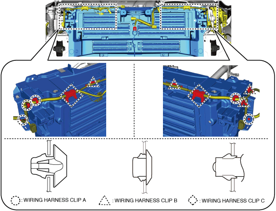
6.Remove wiring harness clips A, B and C secured to the shroud panel.
am3zzw00030353
|
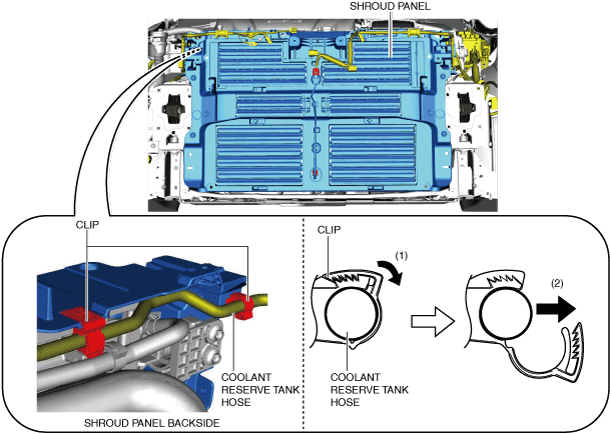
7.Open the clips in the direction of arrow (1) shown in the figure and remove the coolant reserve tank hose in the direction of arrow (2).
am3zzw00023230
|
-
Warning
-
• Remove the radiator from the shroud panel using two people. Otherwise, the radiator may fall and cause injury.
8.Remove the bolts.
am3zzw00023232
|

9.Remove the floor jack which has supported the shroud panel.
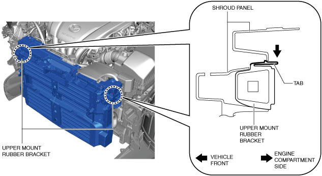
10.Press down the tabs shown in the figure in the direction of the arrow, pull out the upper mount rubber bracket toward the vehicle rear, and remove it.
am3zzw00023233
|
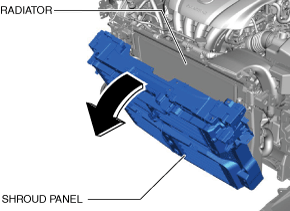
11.Hold the upper part of the radiator by hand and tilt the shroud panel toward the vehicle front.
am3zzw00023234
|
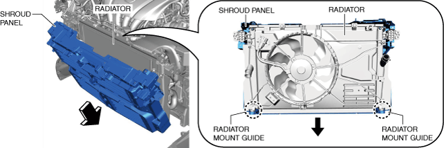
12.Move the shroud panel to the lower side with the radiator held by hand, detach it from the radiator mount guide, and remove the shroud panel toward the vehicle front.
am3zzw00023235
|
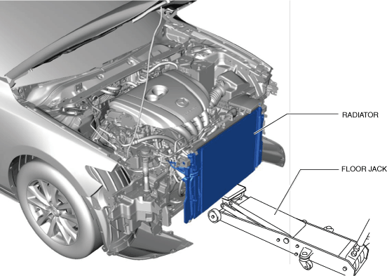
13.Support the radiator using a floor jack at the position shown in the figure.
am3zzw00023236
|
-
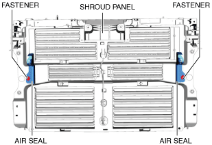
1. Remove the fastener.
 am3zzw000232372. Remove the air seal.
14.Install in the reverse order of removal.
15.Adjust the headlight aiming. (See HEADLIGHT AIMING [(US)].)
16.Perform the 360° view monitor system aiming. (with 360° view monitor system) (See 360°VIEW MONITOR SYSTEM AIMING.)
17.Perform the front radar sensor aiming adjustment. (with front radar sensor) (See FRONT RADAR SENSOR AIMING.)
18.Perform the front side radar sensor aiming adjustment. (with front side radar sensor) (See FRONT SIDE/REAR SIDE RADAR SENSOR AIMING.)