OIL SEAL (CONTROL VALVE BODY) REPLACEMENT [ET6A-EL (US)]
OIL SEAL (CONTROL VALVE BODY) REPLACEMENT [ET6A-EL (US)]
SM2335469
id0517n11187x5
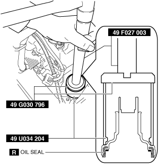
Special Service Tool (SST)
|
49 F027 003
Handle
|
 |
49 G030 796
Body
(Part of 49 G030 795)
|
 |
49 U034 204
Dust boot installer
|
 |
Replacement Part
|
Oil seal
Quantity: 1
Location of use: control valve body
|
Hose clamp
Quantity: 1
Location of use: control valve body
|
1.Disconnect the negative battery terminal. (See NEGATIVE BATTERY TERMINAL DISCONNECTION/CONNECTION [(US)].)
2.Remove the following parts as a single unit. (See INTAKE-AIR SYSTEM REMOVAL/INSTALLATION [SKYACTIV-G (WITHOUT CYLINDER DEACTIVATION (US))].)
-
• Air cleaner cover• Air cleaner element• Fresh-air duct• Air cleaner case• Air hose• Resonance chamber
3.Disconnect the control valve body connector.
am3zzw00022383
|

-
Caution
-
• Make sure that your hand does not touch the terminal as the connector terminal could be damaged.• Water or foreign matter entering the connector can cause a poor connection or corrosion. Be careful not to allow water droplets or foreign matter to get on the connector when disconnecting it.
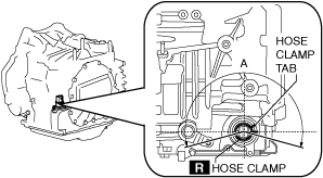
4.Remove the hose clamp.
am3zzw00022384
|

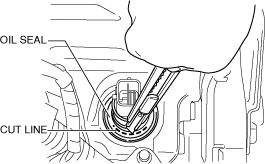
5.Cut the oil seal using a utility knife as shown in the following illustration.
am3uuw00008328
|
-
Caution
-
• Do not damage the transaxle case.• Do not damage the control valve body coupler connector.• To prevent foreign matter penetration, clean the oil seal area thoroughly and cut the oil seal so as not to leave cutting fragments.
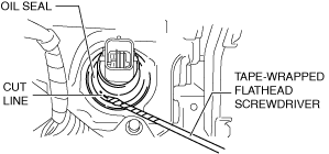
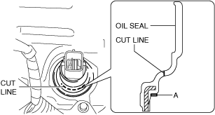
6.Using a tape-wrapped flathead screwdriver, remove the oil seal from the transaxle case.
am3uuw00009191
|
-
Note
-
• Remove the oil seal by tapping the tip of a tape-wrapped flathead screwdriver on the inner circumference surface A area of the oil seal.
 am3zzw00022385
7.Temporarily install the oil seal (control valve body) by hand.
8.Using the SSTs and a hammer, install the oil seal (control valve body) so that it is not tilted and there is no height difference between the transaxle case surface and the end surface of the oil seal.
am3zzw00022386
|
-
Caution
-
• When installing the oil seal (control valve body), do not mistakenly hit the control valve body connector with the hammer. Otherwise the control valve body connector could be damaged making it no longer waterproof.
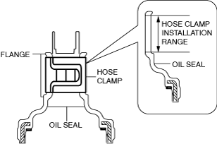
9.Install a new hose clamp to the position shown in the figure.
-
Caution
-
• If the hose clamp is reused it could cause ATF leakage, therefore use a new hose clamp.• Install the hose clamp tab to within the range shown in the figure.ac5uuw00002275
A: 210°
• Install the hose clamp so that it does not interfere with the top and bottom flanges of the oil seal to maintain the waterproofing integrity.am3zzw00022387
10.Connect the control valve body connector.
-
Caution
-
• Make sure that your hand does not touch the terminal as the connector terminal could be damaged.• Verify that there is no fluid or foreign matter adhering to the connector before connecting the connector.• Insert the connector straight as the connector terminal could be damaged.• Rotate the connector lever until a click is heard.
am3zzw00022383
|
11.Install the following parts as a single unit. (See INTAKE-AIR SYSTEM REMOVAL/INSTALLATION [SKYACTIV-G (WITHOUT CYLINDER DEACTIVATION (US))].)
-
• Air cleaner cover• Air cleaner element• Fresh-air duct• Air cleaner case• Air hose• Resonance chamber
12.Connect the negative battery terminal. (See NEGATIVE BATTERY TERMINAL DISCONNECTION/CONNECTION [(US)].)