CLUTCH UNIT REMOVAL/INSTALLATION [C66M-R]
CLUTCH UNIT REMOVAL/INSTALLATION [C66M-R]
SM2335431
id0510ma157200
Special Service Tool (SST)
|
49 E011 1A0
Ring gear brake set
|
 |
49 SE01 310A
Clutch disc center tool
|
 |
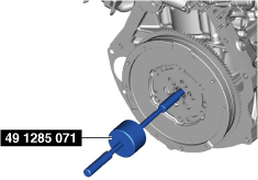
49 1285 071
Bearing puller
|
 |
Replacement Part
|
Lock bolt
Quantity: 6
Location of use: Dual-mass flywheel
|
Pilot bearing
Quantity: 1
Location of use: Dual-mass flywheel
|
Oil and Chemical Type
|
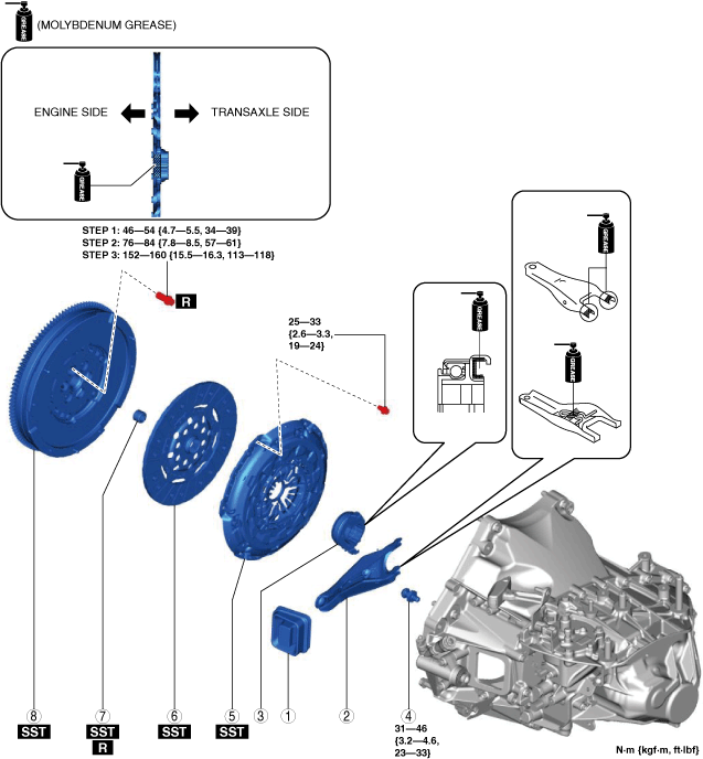
Grease
Type: Molybdenum grease
|
1.Disconnect the negative battery terminal. (See NEGATIVE BATTERY TERMINAL DISCONNECTION/CONNECTION [(US)].)
2.Remove the manual transaxle. (See MANUAL TRANSAXLE REMOVAL/INSTALLATION [C66M-R (SKYACTIV-G 2.0, SKYACTIV-G 2.5) (US)].)
3.Remove in the order indicated in the table.
4.Install in the reverse order of removal.
5.Add the specified amount of manual transaxle oil. (See MANUAL TRANSAXLE OIL REPLACEMENT [C66M-R (US)].)
am3zzw00021631
|
|
1
|
Boot
|
|
2
|
Clutch release fork
|
|
3
|
Clutch release collar
|
|
4
|
Pivot pin
|
|
5
|
Clutch cover
|
|
6
|
Clutch disc
|
|
7
|
Pilot bearing
(See Pilot Bearing Removal Note.)
|
|
8
|
Dual-mass flywheel
|
Clutch Cover And Clutch Disc Removal Note
-
Caution
-
• A function for eliminating set load changes, which occur due to clutch disc wear, is equipped in the clutch cover of the C66M-R manual transaxle. Because the clutch cover deforms once it is used, it can only provide a correct set load when it used with the clutch disc that is equipped with it. Therefore, if the clutch cover or clutch disc is newly replaced, perform the following.
-
― When newly replacing the clutch cover, also newly replace the clutch disc.― When newly replacing the clutch disc, also newly replace the clutch cover.
-
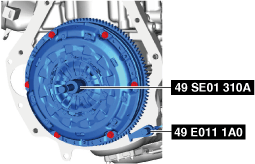
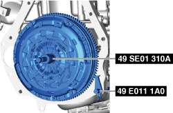
1.Hold the clutch unit using the SSTs (49 SE01 310A, 49 E011 1A0).
am3zzw00021632
|
2.Loosen each bolt in small steps and diagonally.
3.Remove the clutch cover and clutch disc.
Pilot Bearing Removal Note
-
Note
-
• The pilot bearing does not need to be removed unless you are replacing it.
1.Use the SST (49 1285 071) to remove the pilot bearing.
am3zzw00021633
|
Dual-mass Flywheel Removal Note
1.Hold the dual-mass flywheel using the SST (49 E011 1A0).
am3zzw00021634
|
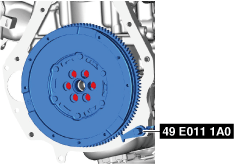
2.Remove the lock bolts, and remove the plate and the dual-mass flywheel.
3.Inspect for oil leakage from the crankshaft rear oil seal.
-
• If there is any malfunction, replace the crankshaft rear oil seal. (See REAR OIL SEAL REPLACEMENT [SKYACTIV-G (WITHOUT CYLINDER DEACTIVATION (US))].) (See REAR OIL SEAL REPLACEMENT [SKYACTIV-G (WITH CYLINDER DEACTIVATION (US))].)
Dual-mass Flywheel Installation Note
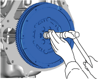
1.Clean the dual-mass flywheel.
-
Caution
-
• When cleaning the dual-mass flywheel, use a dry cloth with no fluid.• Do not clean between the primary flywheel and secondary flywheel. Clean only the bolt connecting areas and the contact surface of the clutch.
2.Clean the crankshaft thread holes.
3.Install the dual-mass flywheel to the crankshaft, and temporarily tighten a new lock bolts.
4.Hold the dual-mass flywheel using the SST (49 E011 1A0).
am3zzw00021635
|
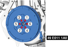
5.Tighten the lock bolts completely in the order shown in the figure in the 3 steps.
Pilot Bearing Installation Note
1.Install new pilot bearing to the specified position using the following tools.
am3zzw00021636
|
-
Tool
-
Snap-on brand millimeter size bushing driver set (A160M) adapter A160M7 (20—22 mm {0.79—0.86 in})
-
• Use the adapter with the 20 mm side of the A160M7 (20—22 mm {0.79—0.86 in}) facing the pilot bearing side.
-
Substitution tool
-
Outer diameter: 21 mm {0.83 in}Inner diameter: 19 mm {0.75 in}
-
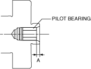
Specified position
-
Distance A of pilot bearing from crankshaft end: 1.5—2.5 mm {0.060—0.098 in}
 am2zzw00010010
Clutch Disc And Clutch Cover Installation Note
-
Caution
-
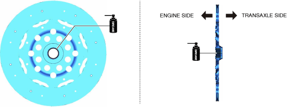
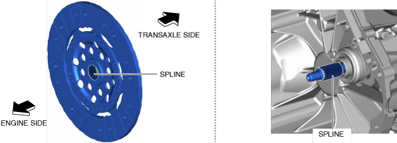
• Do not apply grease to the spline end (transaxle side). If excessive grease is applied, clutch-slip may occur.
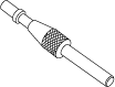
1.Apply grease to the spline (engine side) of the clutch disc.
am3zzw00021637
|
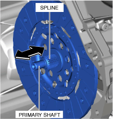
2.Insert the clutch disc into the primary shaft and wipe off the excess grease protruding from the spline.
am3zzw00021638
|
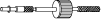
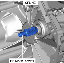
3.Slide the clutch disc three times in the directions of the arrows shown in the figure to engage to grease.
4.Remove the clutch disc from the primary shaft and wipe off the excess grease protruding from the spline.
am3zzw00021639
|
5.Verify that grease has been lightly applied to the clutch disc and the spline of the primary shaft.
am3zzw00021640
|
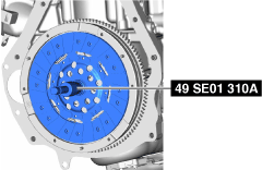
6.Hold the clutch disc position using the SST (49 SE01 310A).
am3zzw00021641
|
7.Hold the clutch unit using the SST (49 E011 1A0).
am3zzw00021642
|
8.Using the following procedure, install the clutch disc and clutch cover.
- (1)Temporarily tighten the bolts in the order shown in the figure.
-
am3zzw00021643
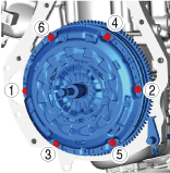
- (2)Tighten the bolts completely in four or five steps in the order shown in the figure and install the clutch disc and cover.
9.Remove the SSTs (49 SE01 310A, 49 E011 1A0).