CRUISE CONTROL SWITCH INSPECTION
CRUISE CONTROL SWITCH INSPECTION
SM2334881
id012000800100
1.Disconnect the negative battery terminal and wait for 1 min or more. (See NEGATIVE BATTERY TERMINAL DISCONNECTION/CONNECTION [(US)].)
2.Remove the driver‐side air bag module. (See DRIVER-SIDE AIR BAG MODULE REMOVAL [TWO-STEP DEPLOYMENT CONTROL SYSTEM – US/CANADA SPEC.].) (See DRIVER-SIDE AIR BAG MODULE INSTALLATION [TWO-STEP DEPLOYMENT CONTROL SYSTEM – US/CANADA SPEC.].) (See DRIVER-SIDE AIR BAG MODULE REMOVAL [STANDARD DEPLOYMENT CONTROL SYSTEM – MEXICO SPEC.].) (See DRIVER-SIDE AIR BAG MODULE INSTALLATION [STANDARD DEPLOYMENT CONTROL SYSTEM – MEXICO SPEC.].)
3.Disconnect the clock spring connector (part wiring harness-side).
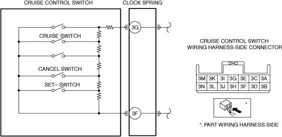
4.Measure the resistance between clock spring terminals 3F and 3G (part wiring harness-side) using a tester.
am3zzw00034779
|
-
• If as specified, go to the next step.• If not as specified, replace the steering switch. (See STEERING SWITCH REMOVAL/INSTALLATION.)
|
Switch condition |
Resistance (ohm) |
|---|---|
|
Cruise switch held at on
|
Approx. 60.4
|
|
CANCEL switch held at on
|
Approx. 301.3
|
|
SET- held at on
|
Approx. 602.3
|
|
Neutral
|
Approx. 1,489.3
|
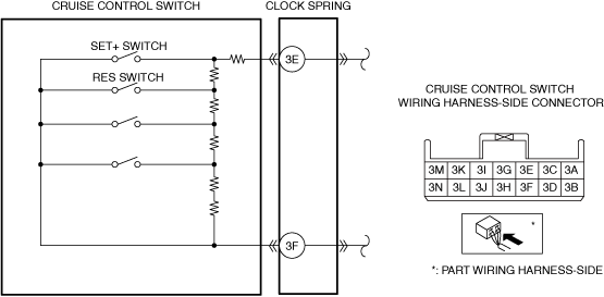
5.Measure the resistance between clock spring terminals 3E and 3F (part wiring harness-side) using a tester.
am3zzw00034790
|
-
• If as specified, go to the next step.• If not as specified, replace the steering switch. (See STEERING SWITCH REMOVAL/INSTALLATION.)
|
Switch condition |
Resistance (ohm) |
|---|---|
|
SET+ switch held at on
|
Continuity
|
|
RES switch held at on
|
Approx. 60.4
|
|
Neutral
|
Approx. 1,489.3
|
6.Apply battery positive voltage to clock spring terminal 3N (part wiring harness-side), and terminal 3B (part wiring harness-side) to ground.
am3zzw00032843
|
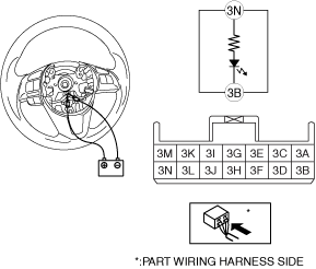
7.Verify that the LED in the steering switch turns on.
-
• If the LED does not illuminate, replace the steering switch. (See STEERING SWITCH REMOVAL/INSTALLATION.)