ELECTRICAL SYSTEM [(US)]
ELECTRICAL SYSTEM [(US)]
SM2334345
id0000000005x1
Electrical Parts
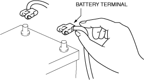
Battery terminal
-
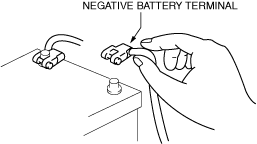
• Before disconnecting connectors or removing electrical parts, disconnect the negative battery terminal.
 ac9uuw00008613
Wiring Harness
am6zzw00008930
|
-
Caution
-
• Do not remove the wiring harness protective tape. Otherwise, the wires could rub against the body, which could result in water penetration and electrical shorting.am6zzw00008931
Connectors
Disconnecting connectors
-
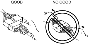
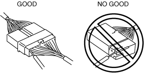
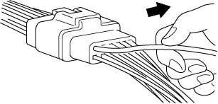
• When disconnecting a connector, grasp the connectors, not the wires.am6zzw00008932• Connectors can be disconnected by pressing or pulling the lock lever as shown.am6zzw00008933

Locking connector
-
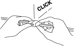
• When locking connectors, listen for a click indicating they are securely locked.am6zzw00008934
Inspection
-
Caution
-
• To prevent damage to the terminal, wrap a thin wire around the tester probe before inserting into terminal.
-
• When a tester is used to inspect for continuity or measuring voltage, insert the tester probe from the wiring harness side.am6zzw00008935• Inspect the terminals of waterproof connectors from the connector side since they cannot be accessed from the wiring harness side.am6zzw00008936
Terminals
Inspection
-
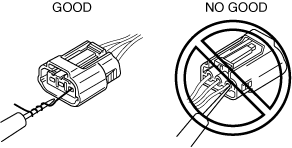
• Pull lightly on individual wires to verify that they are secured in the terminal.am6zzw00008937
Replacement
-
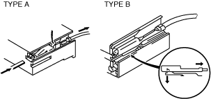
• Use the appropriate tools to remove a terminal as shown. When installing a terminal, be sure to insert it until it locks securely.• Insert a thin piece of metal from the terminal side of the connector and with the terminal locking tab pressed down, pull the terminal out from the connector.am6zzw00008938
Sensors, Switches, and Relays
am6zzw00008939
|
Wiring Harness
Wiring color codes
-
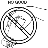
• Two-color wires are indicated by a two-color code symbol.• The first letter indicates the base color of the wire and the second is the color of the stripe.am6zzw00008940
|
CODE |
COLOR |
CODE |
COLOR |
|---|---|---|---|
|
B
|
Black
|
O
|
Orange
|
|
L
|
Blue
|
P
|
Pink
|
|
BR
|
Brown
|
R
|
Red
|
|
DL
|
Dark Blue
|
SB
|
Sky Blue
|
|
DG
|
Dark Green
|
T
|
Tan
|
|
GY
|
Gray
|
V
|
Violet
|
|
G
|
Green
|
W
|
White
|
|
LB
|
Light Blue
|
Y
|
Yellow
|
|
LG
|
Light Green
|
–
|
–
|
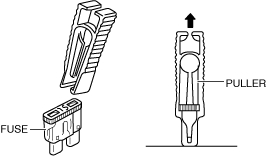
Fuse
Replacement
-
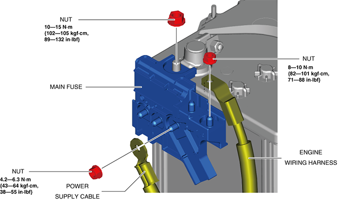
• When replacing a fuse, be sure to replace it with one of the same capacity. If a fuse malfunctions again, the circuit probably has a short and the wiring should be inspected.• Be sure the negative battery terminal is disconnected before replacing a main fuse.am3zzw00025851• When replacing a pullout fuse, use the fuse puller.am6zzw00008941
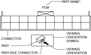
Viewing Orientation for Connectors
Part-side connector
-
• The viewing orientation for part-side connectors is from the terminal side.ac3uuw00001023
*: Part names are shown only when there are multiple connector drawings.
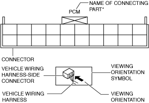
Vehicle harness-side connector
-
• The viewing orientation for vehicle wiring harness-side connectors is from the wiring harness side.ac3uuw00001024
*: With the wiring harness-side connector, connecting part names of all connectors are displayed in the figure.
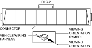
Other
-
• When it is necessary to show the terminal side of the vehicle wiring harness-side connectors, such as the following connectors, the viewing orientation is from the terminal side.
-
― Main fuse block and the main fuse block relays― Data link connector― Check connector― Relay boxam6zzw00008944
-
Female Terminal Fitting Test Procedure
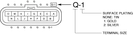
1.Refer to the wiring diagram and verify the location, size, and surface finish plating of the terminal to be tested.
ac9uuw00009737
|
2.Disconnect the negative battery terminal.
3.Disconnect the connector of the terminal to be tested.
-
Caution
-
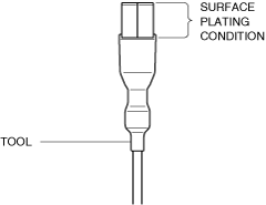
• When performing the fitting test, always use a tool compatible with the surface plating material of the terminal. The terminal surface plating is either gold, silver, or tin (None). Using a tool made of different material may damage the surface plating of the terminal. If the surface plating is damaged, the terminal may erode.ac9uuw00009738• Do not use a tool with scratched surface plating. Using a tool with scratched surface plating may damage the surface plating of the terminal. If the surface plating of the tool is damaged, replace the tool with a new one.• Surface damage is difficult to see. Therefore, always use a magnifying glass when inspecting the condition of the surface plating.ac9uuw00009739
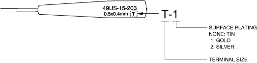
4.Select a suitable tool from the fitting test kit with a size and surface plating that matches the terminal.
-
Caution
-
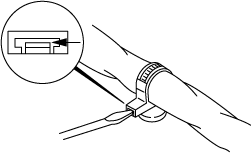
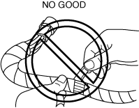
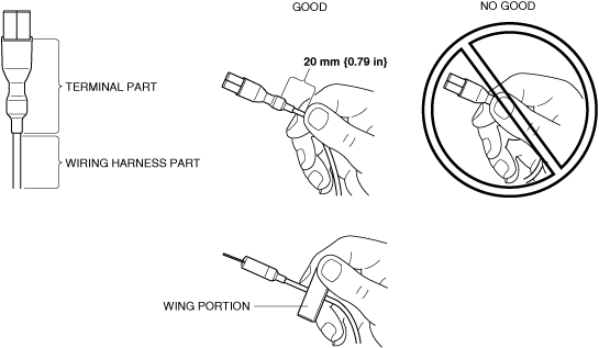
• Slowly insert the tool into the female terminal, and keep the tool in line with the terminal wherever possible.• If the tool is inserted at an angle or wiggled into the female terminal, the terminal may be damaged.• Hold the wing portion of the tool with your fingers (if applicable), or the wiring harness, approximately 20 mm {0.79 in} away from the terminal portion of the tool. If the tool is inserted by holding the terminal portion of the tool, deformation of the female terminal opening can occur due to excessive force.ac5uuw00009447
5.Insert the tool into the female terminal, then slowly pull it out.
-
• The inspection is completed if it can be determined that the terminal connection is good based on how firmly the tool can be inserted and removed.
-
Note
-
• Terminal size L is the largest size terminal tool. It may be difficult to insert it into a female terminal when holding the wiring harness due to excessive resistance. If it appears that the tool may be difficult to insert, confirm that the female terminal is in good condition, prior to inserting the tool.
-
― If the tool cannot be inserted or removed firmly and the condition of the female terminal cannot be determined, go to the next step.
-
-
Caution
-
• If the condition of the female terminal cannot be clearly determined, find the same size and surface treatment of the terminal in a different location to compare the connection firmness. Confirm the terminal location by referring to the wiring diagram.
6.Compare the connection firmness by inserting the tool into an identical terminal (same size and surface treatment) in the same connector.
-
• If the connection is not correct, replace the wiring harness or connectors including the malfunctioning terminal. (Refer to the repair connector replacement procedure.)
Electrical Troubleshooting Tools
Jumper wire
-
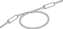
• A jumper wire is used to create a temporary circuit. Connect the jumper wire between the terminals of a circuit to bypass a switch.am6zzw00008945
-
Caution
-
• Do not connect a jumper wire from the power source line to a body ground. This may cause burning or other damage to wiring harnesses or electronic components.
Voltmeter
-
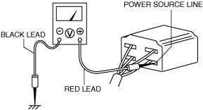
• The direct current voltmeter is used to measure circuit voltage. A voltmeter with a range of 15 V or more is used by connecting the positive (+) probe (red lead wire) to the point where voltage will be measured and the negative (-) probe (black lead wire) to a body ground.am6zzw00008946
Ohmmeter
-
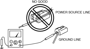
• The ohmmeter is used to measure the resistance between two points in a circuit and to inspect for continuity and short circuits.am6zzw00008947
-
Caution
-
• Do not connect the ohmmeter to any circuit where voltage is applied. This will damage the ohmmeter.
-
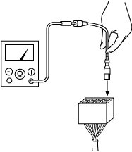
• When using the tool for connecting the ohmmeter to the female terminal, the lead wire of the ohmmeter should be connected to the tool first and then connected to the female terminal. This will help to avoid deformation of the female terminal opening due to excessive force.ac9uuw00009736
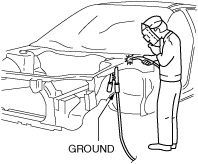
Precautions Before Welding
1.Switch the ignition off (LOCK).
2.Disconnect the battery terminals.
ac9uuw00008614
|
3.Securely connect the welding machine ground near the welding area.
am6zzw00008949
|
4.Cover the peripheral parts of the welding area to protect them from weld spatter.
Ground Inspection And Disconnection/reconnection
-
― Remove the bolt or screw of the ground to inspect for dirt or rust.― If there is any dirt or rust, clean it.― Securely tighten the bolt or screw to the specified tightening torque.― Verify that parts do not interfere with the ground circuit.