TRANSAXLE ASSEMBLY
TRANSAXLE ASSEMBLY
SM2841734
id051500170000
Step 1
1.Perform the primary shaft and secondary shaft preload adjustment and select a shim of the appropriate thickness. (See BEARING PRELOAD ADJUSTMENT.)
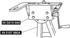
2.Assemble the SST (49 G019 0A0) to the SST (49 0107 680A).
bc61um00000213
|
-
Bolt used
-
Part No.: 9YA02 A220 or M12 ×1.75 length 40 mm {1.6 in}
-
Tightening torque
-
88—118 N·m {9.0—12 kgf·m, 65—87 ft·lbf}
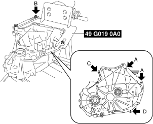
3.Assemble the clutch housing component to the SST.
bc61um00000214
|
-
Bolt A
-
Part No.: 99450 1055 or M10 ×1.25 length 55 mm {2.2 in}, and nut (M10 ×1.25)
-
Bolt A tightening torque
-
38—52 N·m {3.9—5.3 kgf·m, 29—38 ft·lbf}
-
Bolt B
-
SST (49 G019 033 part of 49 G019 0A0)
-
Bolt B tightening torque
-
88—118 N·m {9.0—12 kgf·m, 65—87 ft·lbf}
-
Bolt C
-
Part No.: 9YA02 1080 or M10 ×1.5 length 55 mm {2.2 in}
-
Bolt C tightening torque
-
38—52 N·m {3.9—5.3 kgf·m, 29—38 ft·lbf}
-
Bolt D
-
Part No.: 99450 1030 or M10 ×1.25 length 30 mm {2.2 in}
-
Bolt D tightening torque
-
38—52 N·m {3.9—5.3 kgf·m, 29—38 ft·lbf}
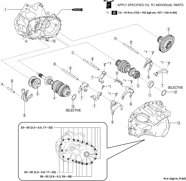
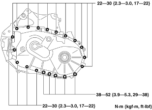
4.Assemble the MTX in the order shown in the figure.
bc61um00000092
|
|
1
|
Clutch housing component
|
|
2
|
Differential
|
|
3
|
Secondary shaft component
|
|
4
|
Primary shaft component
|
|
5
|
Reverse idler gear component
|
|
6
|
Shift fork
|
|
7
|
Shift rod end
|
|
8
|
Shift rod
|
|
9
|
Oil path
|
|
10
|
Magnet
|
|
11
|
bearing outer race
|
|
12
|
shim
|
|
13
|
Transaxle case component
|
Secondary shaft component and primary shaft component assembly note
1. Assemble the secondary shaft component and primary shaft component to the clutch housing component as a single unit.
bc61um00000094
|
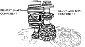
2.Shake the assembled parts and assemble each one completely.
Reverse idler gear component assembly note
1. Pull the reverse idler gear shaft and position it to the location shown in the figure.
bc61um00000139
|
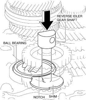
2.Engage each gear while aligning the shim notch with the ball bearing of the primary shaft component.
3.Push the reverse idler gear shaft and assemble the reverse idler gear component.
Shift fork, shift rod end, and shift rod assembly note
1.Assemble the shift fork (1GR/2GR), shift rod end (1GR/2GR), and shift rod (1GR/2GR) using the following procedure:
bc61um00000096
|
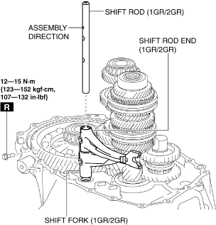
- (1)Assemble the shift fork to the clutch hub sleeve.
- (2)Verify the assembly direction of the shift rod.
-
-
Note
-
• Assemble the shift rod so that the pits used for verifying the assembly direction are facing the transaxle case side and the exterior side of the MTX.
-
- (3)Pass the shift rod through the assembly hole of the shift rod end.
- (4)Pass the shift rod through the assembly hole of the shift fork.
- (5)Assemble the shift rod to the clutch housing.
- (6)Tighten the assembly bolt and assemble the shift fork, shift rod end, and shift rod.
2.Assemble the shift fork (5GR/6GR), shift rod end (5GR/6GR), and shift rod (5GR/6GR) using the following procedure:
bc61um00000097
|
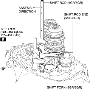
- (1)Assemble the shift fork to the clutch hub sleeve.
- (2)Verify the assembly direction of the shift rod.
-
-
Note
-
• Assemble the shift rod so that the pits used for verifying the assembly direction are facing the transaxle case side and the exterior side of the MTX.
-
- (3)Pass the shift rod through the assembly hole of the shift fork.
- (4)Set the shift rod end to the position shown in the figure and pass the shift rod through the assembly hole of the shift rod end.
- (5)Assemble the shift rod to the clutch housing.
- (6)Tighten the assembly bolt and assemble the shift fork, shift rod end, and shift rod.
3.Assemble the shift fork (reverse) and shift rod (reverse) using the following procedure:
bc61um00000098
|
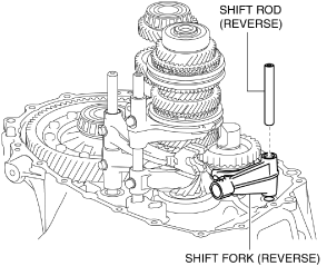
- (1)Assemble the shift fork to the clutch hub sleeve.
- (2)Assemble the shift rod.
4.Assemble the shift fork (3GR/4GR), shift rod end (3GR/4GR), shift rod end (reverse), and shift rod (3GR/4GR) using the following procedure:
bc61um00000099
|
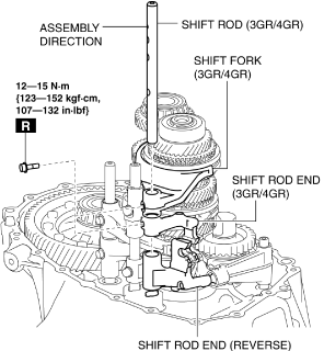
- (1)Assemble the shift fork to the clutch hub sleeve.
- (2)Verify the assembly direction of the shift rod.
-
-
Note
-
• Assemble the shift rod so that the pits used for verifying the assembly direction are facing the transaxle case side and the exterior side of the MTX.
-
- (3)Pass the shift rod through the assembly hole of the shift fork.
- (4)Set the shift rod end (3GR/4GR) to the position shown in the figure and pass the shift rod through the assembly hole of the shift rod end (3GR/4GR).
- (5)Set the shift rod end (reverse) to the position shown in the figure and pass the shift rod through the assembly hole of the shift rod end (reverse).
- (6)Assemble the shift rod to the clutch housing.
- (7)Tighten the assembly bolt and assemble the shift fork, shift rod end, and shift rod.
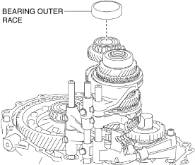
Bearing outer race, shim, Transaxle case component assembly note
1.Assemble the bearing outer race to the secondary shaft component.
bc61um00000165
|
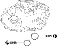
2.Assemble the shims.
bc61um00000166
|
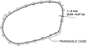
3.Apply silicone sealant to the transaxle case component as shown in the figure.
bc61um00000100
|
4.Assemble the transaxle case component.
bc61um00000215
|
-
Caution
-
• Assemble the transaxle case component before the applied silicone sealant starts to harden.
Step 2
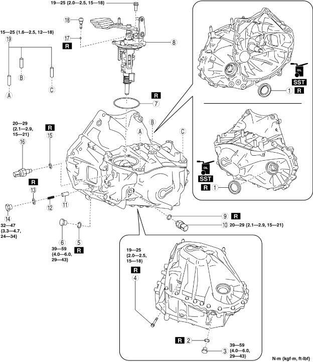
1.Assemble the parts around the MTX in the order shown in the figure.
bc61um00000093
|
|
1
|
Oil seal
|
|
2
|
Gasket
|
|
3
|
Drain plug
|
|
4
|
Reverse gear shaft anchor bolt
|
|
5
|
Gasket
|
|
6
|
Oil level plug
|
|
7
|
O-ring
|
|
8
|
Shift control module
|
|
9
|
Gasket
|
|
10
|
Back-up light switch
|
|
11
|
Detent ball pin
|
|
12
|
Spring
|
|
13
|
Gasket
|
|
14
|
Plug
|
|
15
|
Gasket
|
|
16
|
Neutral switch
|
|
17
|
O-ring
|
|
18
|
Breather
|
|
19
|
Stud bolt
|
Oil seal assembly note
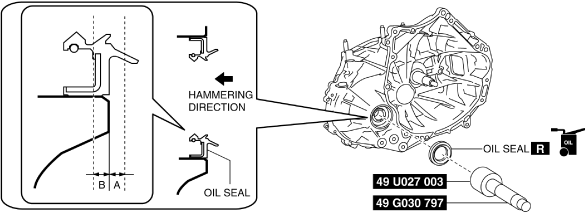
1. Assemble a new oil seal (LH) to the transaxle case using the SSTs.
bc61um00000216
|
-
A: 0.3 mm {0.01 in}B: 0.3 mm {0.01 in}
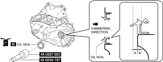
2. Assemble a new oil seal (RH) to the clutch housing using the SSTs.
bc61um00000217
|
-
A: 0.3 mm {0.01 in}B: 0.3 mm {0.01 in}