CYLINDER BLOCK DISASSEMBLY (II)
CYLINDER BLOCK DISASSEMBLY (II)
SM2841681
id011000500700
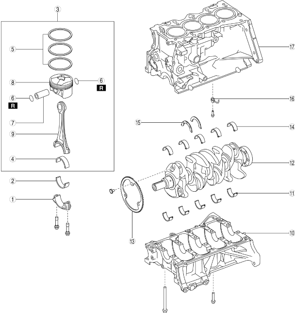
1.Disassemble in the order indicated in the table.
btstze00000008
|
|
1
|
Connecting rod cap
|
|
2
|
Lower connecting rod bearing
|
|
3
|
Piston, connecting rod
|
|
4
|
Upper connecting rod bearing
|
|
5
|
Piston ring
|
|
6
|
Snap ring
(See Snap Ring Disassembly Note.)
|
|
7
|
Piston pin
|
|
8
|
Piston
|
|
9
|
Connecting rod
|
|
10
|
Lower cylinder block
|
|
11
|
Lower main bearing
|
|
12
|
Crankshaft
(See Crankshaft Disassembly Note.)
|
|
13
|
Plate
|
|
14
|
Upper main bearing
|
|
15
|
Thrust bearing
|
|
16
|
Oil jet valve
|
|
17
|
Upper cylinder block
|
Connecting Rod Cap Disassembly Note
1.Before removing the connecting rod cap, inspect the connecting rod side clearance. (See CONNECTING ROD CLEARANCE INSPECTION.)
bp31je00000044
|
2.The removed connecting rod caps are to be kept so that they can be assembled to the same positions and in the direction as before removal.
Connecting Rod Bearing Disassembly Note
1.The removed connecting rod bearings are to be kept so that they can be assembled to the same positions and in the direction as before removal.
Piston, Connecting Rod Disassembly Note
1.Before removing the piston and connecting rod, remove the carbon in the cylinder.
2.Before removing the piston and connecting rod, inspect the oil clearance at the large end of the connecting rod. (See CONNECTING ROD CLEARANCE INSPECTION.)
Snap Ring Disassembly Note
1.Before removing the snap ring, inspect that the large end of connecting rod drops under its own weight with no resistance. (See PISTON AND CONNECTING ROD INSPECTION.)
2.Remove the snap ring using a flathead screwdriver.
bpe2ue00000022
|

Lower Cylinder Block Disassembly Note
1.Before removing the lower cylinder block, inspect the crankshaft end play. (See CRANKSHAFT INSPECTION.)
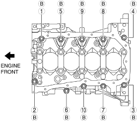
2.Loosen the lower cylinder block installation bolts B in two or three passes in the order shown in the figure and remove them.
bpe1ze00000039
|
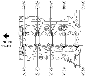
3.Loosen the lower cylinder block installation bolts A in two or three passes in the order shown in the figure and remove them.
bpe1ze00000040
|
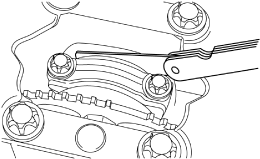
4.Using a screwdriver wrapped in a cloth, peel the sealant away a little at a time, and remove the lower cylinder block.
bpe2ue00000025
|
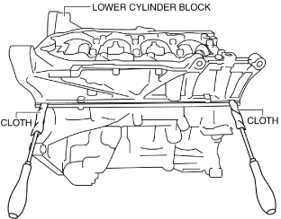
-
Caution
-
• Do not apply excessive force to the screwdriver. Otherwise, the lower cylinder block could be damaged.• Be careful not to scratch or damage the seal surface. Otherwise, it could cause oil leakage.
Thrust Bearing And Main Bearing Disassembly Note
1.The removed thrust bearings and main bearings are to be kept so that they can be assembled to the same positions and in the direction as before removal.
Crankshaft Disassembly Note
-
Caution
-
• Placing the crankshaft on a disassembly bench will deform or damage it because the plate for the crankshaft position sensor signal detection installed to the crankshaft is larger than the counterweight. Therefore, set wood blocks or similar objects on the both sides of the crankshaft so that the plate does not contact the disassembly bench directly when placing the crankshaft on it bench.