TIMING CHAIN DISASSEMBLY
TIMING CHAIN DISASSEMBLY
SM2841616
id011000505500
-
Caution
-
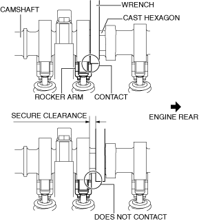
• If the camshaft is rotated with the timing chain removed and the piston at the top dead center position, the valve may contact the piston and the engine could be damaged. When rotating the camshaft with the timing chain removed, rotate it after lowering the piston from the top dead center position.• When rotating the camshaft using a wrench on the cast hexagon, the wrench may contact the rocker arm and damage the rocker arm. To prevent damage to the rocker arm when holding the camshaft on the cast hexagon, use a wrench on the rear side of the engine as shown in the figure to secure a clearance between the cam.
 am3uuw00008837
-
Note
-
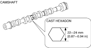
• Width at the cast hexagon of the camshaft is 22—24 mm {0.87—0.94 in}.am3uuw00009029
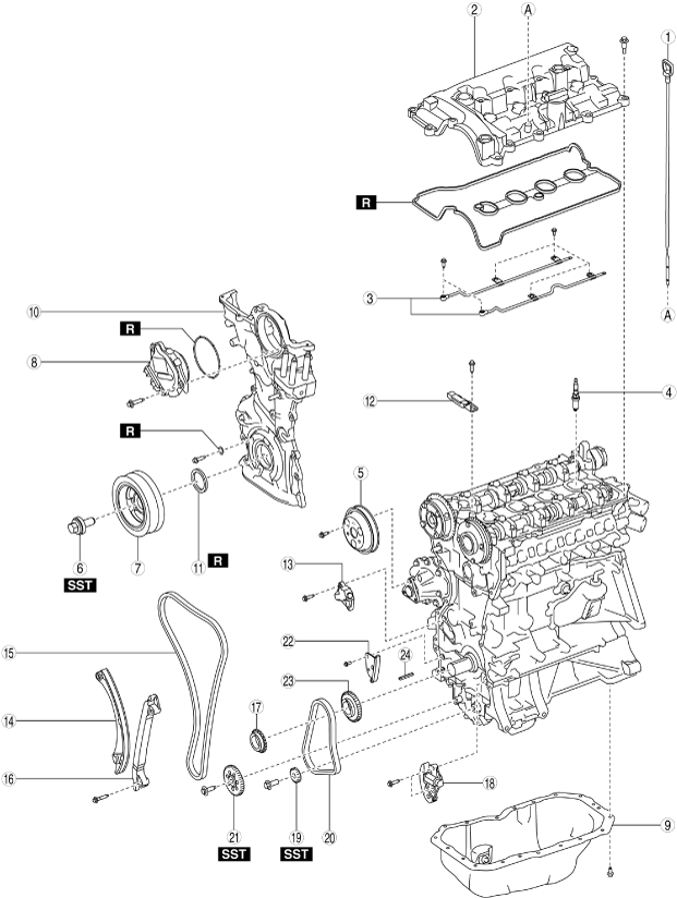
1.Disassemble in the order indicated in the table.
bpe1ze00000062
|
|
1
|
Dipstick
|
|
2
|
Cylinder head cover
|
|
3
|
Oil shower pipe
|
|
4
|
Spark plug
|
|
5
|
Water pump pulley
|
|
6
|
Crankshaft pulley lock bolt
|
|
7
|
Crankshaft pulley
|
|
8
|
Electric variable valve timing motor/driver
|
|
9
|
Oil pan
(See Oil Pan Disassembly Note.)
|
|
10
|
Engine front cover
|
|
11
|
Front oil seal
|
|
12
|
Chain guide (No.1)
|
|
13
|
Chain tensioner
|
|
14
|
Tensioner arm
|
|
15
|
Timing chain
|
|
16
|
Chain guide (No.2)
|
|
17
|
Crankshaft sprocket
|
|
18
|
Oil pump chain tensioner
|
|
19
|
Balancer shaft sprocket
|
|
20
|
Oil pump chain
|
|
21
|
Oil pump driven sprocket
|
|
22
|
Oil pump chain guide
|
|
23
|
Oil pump drive sprocket
|
|
24
|
Key
|
Water Pump Pulley Disassembly Note
-
Caution
-
• Be careful not to damage the belt groove and surface of the water pump pulley when using tools, otherwise it will cause wear, breakage, abnormal noise of the drive belt (stretch belt), damage to the pulley, and rust.
1.Align the water pump pulley hole with the water pump hole as shown in the figure.
am3uuw00008841
|
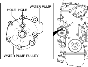
2.Insert an appropriate bolt (length approx. 70 mm {2.8 in}) into the water pump hole as shown in the figure, and lock the water pump pulley against rotation.
am3uuw00008842
|
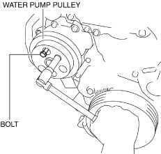
3.Remove the water pump pulley.
4.Remove the bolt used for locking the water pump pulley against rotation.
Crankshaft Pulley Lock Bolt Disassembly Note
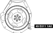
1.Hold the crankshaft using the SST.
bpe1ze00000063
|
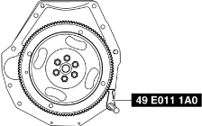
2.Remove the crankshaft pulley lock bolt.
Oil Pan Disassembly Note
1.Remove the oil pan using a separator tool.
adejjw00003946
|
Engine Front Cover Disassembly Note
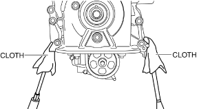
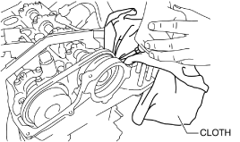
1.Remove the engine front cover installation bolts.
2.Using a screwdriver wrapped in a cloth, peel the sealant away a little at a time, and remove the engine front cover.
-
Caution
-
• Do not apply excessive force to the screwdriver. Otherwise, the engine front cover could be damaged.• Be careful not to scratch or damage the seal surface. Otherwise, it could cause oil leakage.am3uuw00008851am3uuw00008852
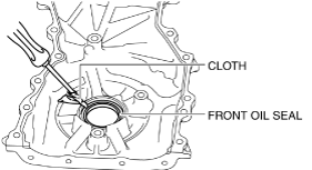
Front Oil Seal Disassembly Note
1.Remove the oil seal using a flathead screwdriver with the tip protected by a clean cloth.
bpe2ue00000100
|
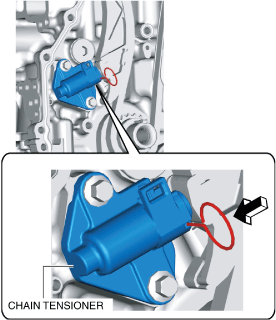
Chain Tensioner Disassembly Note
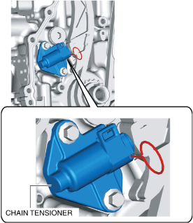
1.Verify the chain tensioner shape and identify the chain tensioner type.
ac4ccw00002689
|
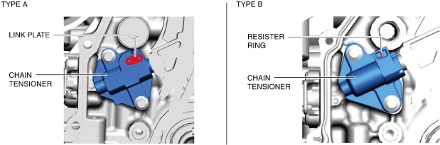
-
Note
-
• Verifying the chain tensioner type is necessary because the following procedures may differ according to the type of tensioner.
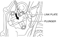
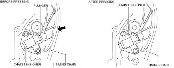
2.While moving the exhaust camshaft back and forth in the direction of the arrow using a wrench on the cast hexagon, press down the link plate of the timing chain tensioner using a precision screwdriver and release the plunger lock. (Chain tensioner (type A))
bp31je00000104
|
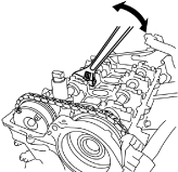
am3uuw00008854
|
-
Note
-
• When moving the exhaust camshaft back and forth, the timing chain pushes the plunger in the chain tensioner making it easier to operate the link plate.
3.Push back the plunger slowly in the direction shown in the figure with the link plate still pushed down. (Chain tensioner (type A))
am3uuw00008855
|
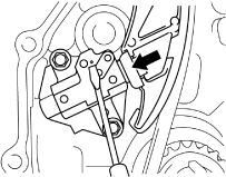
4.Remove the screwdriver from the link plate with the plunger still pushed down. (Chain tensioner (type A))
5.Release the force slightly from the plunger, and move it back and forth 2—3 mm {0.08—0.11 in}. (Chain tensioner (type A))
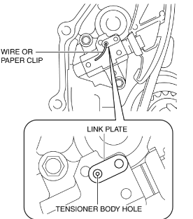
6.Insert a wire with an approx. diameter of 1.5 mm {0.059 in} or a paper clip where the link plate hole and the tensioner body hole overlap to secure the link plate and lock the plunger. (Chain tensioner (type A))
am3uuw00008856
|
7.Loosen the chain tensioner using the following procedure: (Chain tensioner (type B))
- (1)Insert a metal rod (diameter approx. 1.4 mm {0.055 in}, length approx. 55 mm {2.2 in}) into the hole in the body of the chain tensioner.
-
amxzzw00003020
- (2)Press the resister ring and unlock the plunger.
-
amxzzw00003021
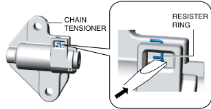
- (3)Press the timing chain in the direction of the arrow and press in the chain tensioner plunger to the position where the groove and body hole are aligned.
-
amxuuw00004405
- (4)With the plunger pressed in, further insert the metal rod set in (1) above.
-
amxzzw00003022
-
Note
-
• The rod secures the plunger and releases the tension.
-
- (5)Loosen the power of the hand pressing the plunger and verify that the pressed-in rod does not move.
8.Remove the chain tensioner.
Oil Pump Chain Disassembly Note
1.Hold the crankshaft using the SST.
bpe1ze00000095
|
2.Slightly loosen the balancer shaft sprocket and oil pump driven sprocket installation bolts.
-
Note
-
• At this stage, only loosen the installation bolts, do not remove them. Remove the bolts after removing the oil pump chain tensioner.
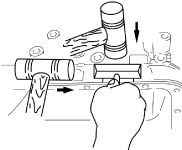
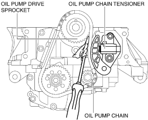
3.Set a cloth wrapped flathead screwdriver in the gap between the oil pump drive sprocket and the oil pump chain as shown in the figure.
bpe1ze00000064
|
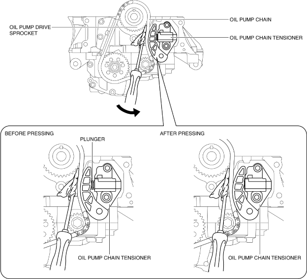
4.Move the screwdriver in the direction of the arrow and press the oil pump chain, and then press on the plunger of the oil pump chain tensioner.
bpe1ze00000065
|
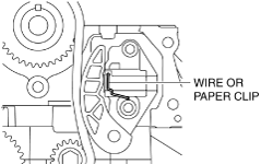
5.Insert a wire with an approx. diameter of 1.4 mm {0.055 in} or a paper clip into the body hole of the oil pump chain tensioner with the plunger pressed.
bpe1ze00000066
|
-
Note
-
• The wire or paper clip secures the plunger, and the tension can be released.
6.Remove the oil pump chain tensioner.
7.Remove the oil pump chain and balancer shaft sprocket as a single unit.
8.Remove the oil pump driven sprocket.