CYLINDER BLOCK ASSEMBLY (II)
CYLINDER BLOCK ASSEMBLY (II)
SM2841612
id011000504100
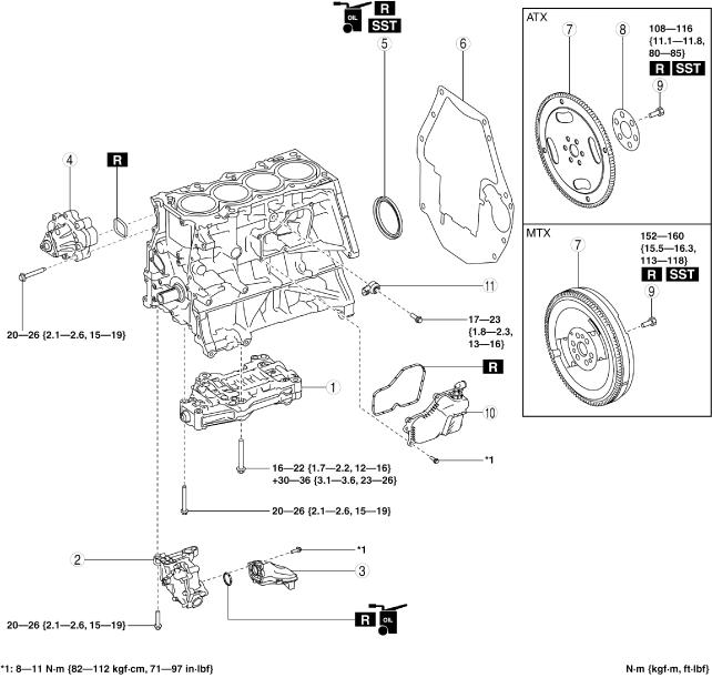
1.Assemble in the order indicated in the table.
bpe5ue00000005
|
|
1
|
Balancer unit
(See Balancer Unit Assembly Note.)
|
|
2
|
Oil pump
(See Oil Pump Assembly Note.)
|
|
3
|
Oil strainer
|
|
4
|
Water pump
(See Water Pump Assembly Note.)
|
|
5
|
Rear oil seal
(See Rear Oil Seal Assembly Note.)
|
|
6
|
End plate
(See End Plate Assembly Note.)
|
|
7
|
Dual-mass flywheel (MTX), drive plate (ATX)
|
|
8
|
Backing plate (ATX)
|
|
9
|
Dual-mass flywheel (MTX)/ drive plate (ATX) installation bolt
|
|
10
|
Oil separator
|
|
11
|
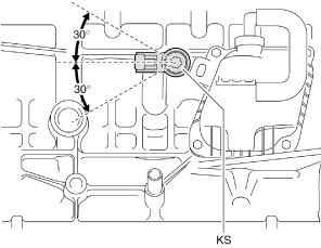
Knock sensor (KS)
|
Balancer Unit Assembly Note
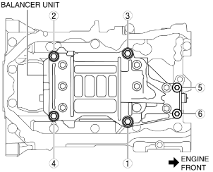
1.Assemble the balancer unit using the following procedure:
- (1)Tighten the bolts in the order shown in the figure.
-
 bpe1ze00000051
Tightening torque
Installation position
Tightening torque
1—416—22 N·m {1.7—2.2 kgf·m, 12—16 ft·lbf}5, 620—26 N·m {2.1—2.6 kgf·m, 15—19 ft·lbf}
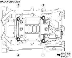
- (2)Retighten the bolts in the order of the numbers indicated in the figure.
-
bpe1ze00000052
-
Tightening torque
-
30—36 N·m {3.1—3.6 kgf·m, 23—26 ft·lbf}
-
Oil Pump Assembly Note
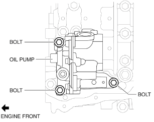
1.Install the oil pump using the following procedure:
- (1)Temporarily tighten the three bolts shown in the figure.
-
bpe1ze00000053
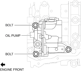
- (2)Tighten the two bolts shown in the figure to the specified torque.
-
bpe1ze00000054
-
Note
-
• The tightening order for the two bolts is optional.
-
Tightening torque
-
20—26 N·m {2.1—2.6 kgf·m, 15—19 ft·lbf}
-
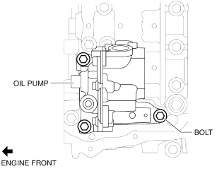
- (3)Finally, tighten the bolt shown in the figure to the specified torque.
-
bpe1ze00000055
-
Tightening torque
-
20—26 N·m {2.1—2.6 kgf·m, 15—19 ft·lbf}
-
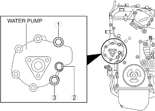
Water Pump Assembly Note
-
Caution
-
• Assemble the water pump gasket to the correct direction shown in the figure. Otherwise, it could leak engine coolant and damage the engine.bpe2ue00000053
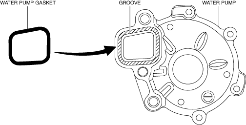
1.Insert a new water pump gasket into the water pump groove.
2.Install the water pump.
3.Tighten the bolts in the order shown in the figure.
bpe2ue00000054
|
-
Tightening torque
-
20—26 N·m {2.1—2.6 kgf·m, 15—19 ft·lbf}
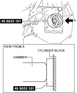
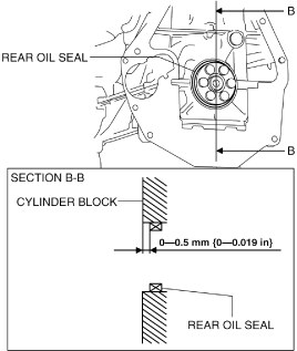
Rear Oil Seal Assembly Note
1.Apply clean engine oil to the inner surface of a new rear oil seal.
2.Insert the rear oil seal into the cylinder block by hand.
3.Tap the oil seal in evenly using the SST and a hammer.
bpe1ze00000056
|
bpe5ue00000006
|
-
Rear oil seal press on amount
-
0—0.5 mm {0—0.019 in}
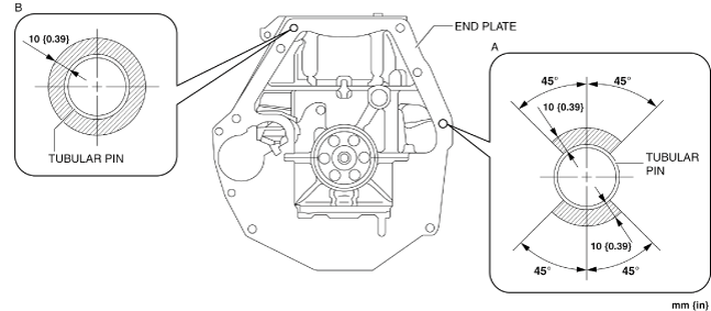
End Plate Assembly Note
1.After end plate assembly, crimp the parts A and B shown in the figure.
bpe5ue00000030
|
-
Crimp procedure
-
Crimp depth: 0.1—1.0 mm {0.004—0.039 in}Crimp width: 0.5—10.0 mm {0.02—0.39 in}Crimp locations: Part A is 1 or more on one-side within shaded area and part B is 2 or more within shaded areas
2.After crimping, verify that there is no damage and removal of the end plate.
Dual-mass Flywheel (MTX)/ Drive Plate (ATX) Installation Bolt Assembly Note
Dual-mass flywheel installation bolt (MTX)
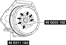
1.Hold the crankshaft using the SST (49 E011 1A0).
2.Temporarily tighten the new bolts.
-
Note
-
• If the dual-mass flywheel (secondary flywheel side) is not positioned properly, perform the following procedure to install it:
- (1)Temporarily tighten the new bolts to the position as shown in the figure.
-
am6zzw00011777
- (2)Install the SST (49 S120 710) to the dual-mass flywheel.
-
am6xuw00005541
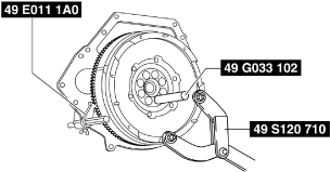
- (3)Rotate the dual-mass flywheel (secondary flywheel side) using the SST (49 S120 710), and then temporarily tighten the remaining new bolt after removing the SST (49 G033 102).
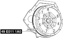
3.Tighten the new bolts in two or three passes in the order shown in the figure.
ac5wzw00005664
|
-
Tightening torque
-
152—160 N·m {15.5—16.3 kgf·m, 113—118 ft·lbf}
Drive plate installation bolt (ATX)
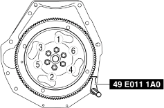
1.Hold the crankshaft using the SST.
2.Tighten the new bolts in two or three passes in the order shown in the figure.
bpe1ze00000093
|
-
Tightening torque
-
108—116 N·m {11.1—11.8 kgf·m, 80—85 ft·lbf}
Knock Sensor (KS) Assembly Note
bpe5ue00000031
|