CYLINDER BLOCK ASSEMBLY (I)
CYLINDER BLOCK ASSEMBLY (I)
SM2841611
id011000504000
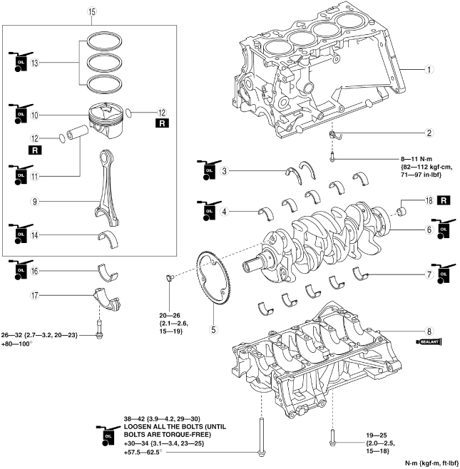
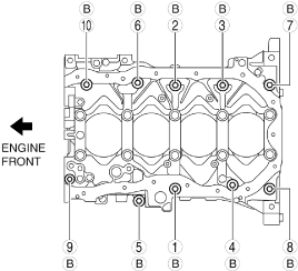
1.Assemble in the order indicated in the table.
bpe5ue00000004
|
|
1
|
Upper cylinder block
|
|
2
|
Oil jet valve
|
|
3
|
Thrust bearing
|
|
4
|
Upper main bearing
|
|
5
|
Plate
(See Plate Assembly Note.)
|
|
6
|
Crankshaft
|
|
7
|
Lower main bearing
|
|
8
|
Lower cylinder block
|
|
9
|
Connecting rod
|
|
10
|
Piston
|
|
11
|
Piston pin
(See Piston Pin Assembly Note.)
|
|
12
|
Snap ring
(See Snap Ring Assembly Note.)
|
|
13
|
Piston ring
(See Piston Ring Assembly Note.)
|
|
14
|
Upper connecting rod bearing
|
|
15
|
Piston, connecting rod
|
|
16
|
Lower connecting rod bearing
|
|
17
|
Connecting rod cap
|
|
18
|
Pilot bearing (MTX)
(See Pilot Bearing Assembly Note.)
|
Thrust Bearing And Main Bearing Assembly Note
-
Caution
-
• If the thrust bearings and main bearings are reused, assemble the bearings to the same positions and in the direction as before removal to prevent engine damage due to seizure or burning of the bearing.• To prevent engine damage due to seizure or burning of the bearing, apply engine oil to the sliding part when assembling.
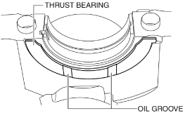
Thrust bearing
1.Apply clean engine oil to the thrust bearings.
2.Assemble the bearings with the oil groove of the thrust bearing pointed toward the sliding surface.
bpe5ue00000016
|
Main bearing
1.Apply clean engine oil to the main bearings.
2.Align the positioning tab of the main bearing with the positioning groove of the lower and upper cylinder block, and assemble the bearings.
bpe5ue00000017
|
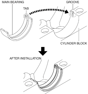
Plate Assembly Note
-
Caution
-
• Placing the crankshaft on a disassembly bench will deform or damage it because the plate for the crankshaft position sensor signal detection installed to the crankshaft is larger than the counterweight. Therefore, set wood blocks or similar objects on the both sides of the crankshaft so that the plate does not contact the disassembly bench directly when placing the crankshaft on it bench.
1.Install the plate using the following procedure:
- (1) Install the groove of the plate tooth to the position shown in the figure and temporarily tighten bolt A.
-
 bpe5ue00000018
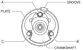
- (2)Temporarily tighten the bolt B.
- (3)Install bolt C and tighten the bolts to the specified tightening torque in the order of C, B, and A.
-
-
Tightening torque
-
20—26 N·m {2.1—2.6 kgf·m, 15—19 ft·lbf}
-
Lower Cylinder Block Assembly Note
1.Completely clean and remove any oil, dirt, sealant or other foreign matter that may be adhering to the lower cylinder block and cylinder block.
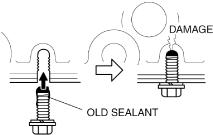
2.When reusing the lower cylinder block installation bolts, clean any old sealant from the bolts.
-
Caution
-
• Apply silicon sealant in a single, unbroken line.• To prevent silicon sealant from hardening, adhere the engine front cover and the cylinder block firmly within 10 min. after applying silicon sealant. After adhering them, tighten the installation bolts immediately.• Using bolts with the old seal adhering could cause cracks in the cylinder block.bpe5ue00000019
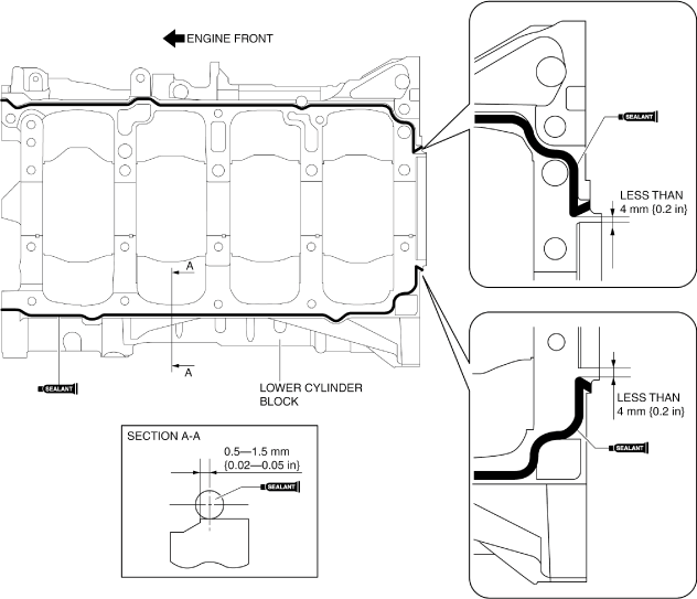
3.Apply silicon sealant to the lower cylinder block shown in the figure.
bpe1ze00000046
|
-
Bead thickness
-
2—6 mm {0.1—0.2 in}
4.Install the lower cylinder block.
5.Tighten the lower cylinder block installation bolts using the following procedure:
- (1)Apply clean engine oil to the seating surface and thread of lower cylinder block installation bolts A.
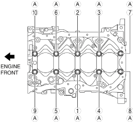
- (2)Tighten lower cylinder block installation bolts A in the order shown in the figure using the following procedure:
-
bpe5ue00000020
-
Tightening procedure
-
Step 1: 38—42 N·m {3.9—4.2 kgf·m, 29—30 ft·lbf}Step 2: Loosen all the bolts (until bolts are torque-free).Step 3: 30—34 N·m {3.1—3.4 kgf·m, 23—25 ft·lbf}Step 4: 57.5—62.5°
-
- (3)Tighten the lower cylinder block installation bolts B in the order shown in the figure.
-
bpe5ue00000021
-
Tightening torque
-
19—25 N·m {2.0—2.5 kgf·m, 15—18 ft·lbf}
-
6.After verifying that silicone sealant protrudes to the rear oil seal press-in part, wipe away the excess silicone sealant.
-
• If silicone sealant does not protrude to the rear oil seal press-in part, remove the lower cylinder block and apply silicone sealant again.
Piston Pin Assembly Note
1.Apply clean engine oil to the piston pin.
2.Insert the piston pin to the piston and connecting rod.
-
Note
-
• When assembling the piston to the connecting rod, each one can be assembled in either direction.
Snap Ring Assembly Note
-
Caution
-
• Do not compress the outer diameter of the snap ring more than necessary when assembling the snap ring (20.66 mm {0.8134 in} or less).
1.Insert a new snap ring using a thin plier.
Piston Ring Assembly Note
-
Note
-
• It is not required to position the end gap between the top ring and second ring.
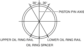
1.Assemble the oil ring so that the end gap of each oil ring rail does not overlap as shown in the figure.
bpe5ue00000022
|
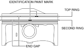
2.Assemble so that the identification paint marks on the top and second rings are visible to the right side of each end gap.
bpe5ue00000023
|
-
Note
-
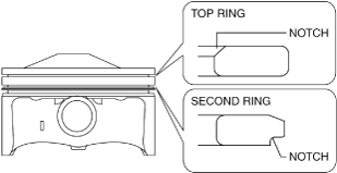
• If there are no identification paint marks, assemble the rings as follows:bpe5ue00000024
-
Top ring
-
― Assemble the ring with the notch (large side) on the inner circumference of the ring at the top.
-
Second ring
-
― Assemble the ring with the notch on the outer circumference of the ring pointing downward.
-
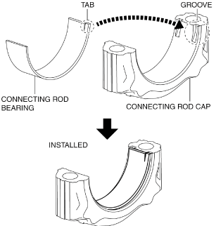
Connecting Rod Bearing Assembly Note
-
Caution
-
• If a connecting rod bearing is reused, assemble it to the same position and in the direction as before removal to prevent engine damage due to seizure or burning of the bearing.• To prevent engine damage due to seizure or burning of the bearing, apply engine oil to the sliding part when assembling.
1.Apply engine oil to the connecting rod bearings.
2.Align the positioning tab of the connecting rod bearing with the positioning groove of the connecting rod and connecting rod cap, and assemble the bearings.
bpe5ue00000025
|
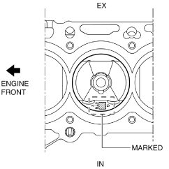
Piston, Connecting Rod Assembly Note
1.Insert the piston into the cylinder with the mark on top of the piston facing the intake side.
bpe5ue00000026
|
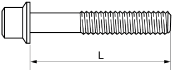
Connecting Rod Cap Assembly Note
-
Caution
-
• When assembling the connecting rod caps, align the broken, rough faces of the connecting rods and connecting rod caps.• If the following condition is met, replace the connecting rod cap bolts.
-
― Length exceeds maximum specificationbpe5ue00000027
-
-
Standard connecting rod cap bolt length
-
43.7—44.3 mm {1.73—1.74 in}
-
Maximum connecting rod cap bolt length
-
45.0 mm {1.77 in}
1.Position so that the broken, rough faces of the connecting rods and connecting rod caps are aligned exactly, and assemble the connecting rod caps.
2.Tighten the connecting rod cap bolts in the following two steps.
-
Tightening procedure
-
Step 1: 26—32 N·m {2.7—3.2 kgf·m, 20—23 ft·lbf}Step 2: 80—100°
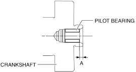
Pilot Bearing Assembly Note
1.Install new pilot bearing to the specified position using the following tools.
bpe5ue00000028
|
-
Tool
-
Snap-on brand millimeter size bushing driver set (A160M) adapter A160M7 (20—22 mm {0.79—0.86 in})
-
• Use the adapter with the 20 mm {0.79 in} side of the A160M7 (20—22 mm {0.79—0.86 in}) facing the pilot bearing side.
-
Substitution tool
-
Outer diameter: 21 mm {0.83 in}Inner diameter: 19 mm {0.75 in}
-
Standard pilot bearing position
-
Distance A of pilot bearing from crankshaft end: 1.5—2.5 mm {0.060—0.098 in}bpe5ue00000029