ERROR IS DISPLAYED ON VEHICLE IDENTIFICATION [VEHICLE INFORMATION ACQUISITION] SCREEN [(US)]
ERROR IS DISPLAYED ON VEHICLE IDENTIFICATION [VEHICLE INFORMATION ACQUISITION] SCREEN [(US)]
SM2566476
id1002x1005400
-
Caution
-
• Perform the following malfunction diagnosis only when vehicle identification [VEHICLE INFORMATION ACQUISITION] is not passed according to the [TROUBLESHOOTING PROCEDURE]. (See TROUBLESHOOTING PROCEDURE [(US)].)
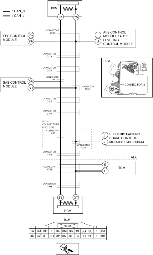
System Wiring Diagram
am3zzw00027503
|
Determination Procedure
-
Caution
-
• When disconnecting the connector, verify that there is no looseness, damage, deformation, corrosion, or poor connection of the connector terminals.• When inspecting the connector, touch it with a paper clip or similar thin pin without directly inserting a tester probe into the terminal.• Disconnect the negative battery cable before performing any work that requires handling of connectors.
|
Step |
Inspection |
Action |
|
|---|---|---|---|
|
1
|
INSPECT FOR SHORT TO GROUND IN CAN-BUS NO.1
• Switch the ignition off.
• Disconnect the negative battery cable. (See NEGATIVE BATTERY TERMINAL DISCONNECTION/CONNECTION [(US)])
• Inspect for continuity at the following terminals:
• Is there continuity?
|
Yes
|
Short to ground in CAN-BUS No.1 has occurred.
Determine the location of a short to ground according to the diagnosis procedure for determining the location of a short to ground in CAN-BUS No.1.
|
|
No
|
Go to the next step.
|
||
|
2
|
INSPECT FOR SHORT TO POWER SUPPLY IN CAN-BUS No.1
• Connect the negative battery cable. (See NEGATIVE BATTERY TERMINAL DISCONNECTION/CONNECTION [(US)].)
• Switch the ignition ON (engine off).
• Measure the voltage at body control module (BCM) terminal 3X and 3W.
• Is the voltage between 1.5—3.5 V?
|
Yes
|
Go to the next step.
|
|
No
|
Short to power supply in CAN-BUS No.1 has occurred.
Determine the location of a short to power supply according to the diagnosis procedure for determining the location of a short to power supply in CAN-BUS No.1.
|
||
|
3
|
INSPECT FOR SHORT BETWEEN CIRCUITS IN CAN-BUS No.1
• Measure the voltage at body control module (BCM) terminals 3X and 3W.
• Is the voltage at body control module (BCM) terminals 3X and 3W the same?
|
Yes
|
Short between circuits in CAN-BUS No.1 has occurred.
Determine the location of a short between circuits according to the diagnosis procedure for determining the location of a short between circuits in CAN-BUS No.1.
|
|
No
|
Go to the next step.
|
||
|
4
|
INSPECT FOR OPEN CIRCUIT IN THE WIRING HARNESS BETWEEN PCM AND BODY CONTROL MODULE (BCM)
• Switch the ignition off.
• Disconnect the negative battery cable. (See NEGATIVE BATTERY TERMINAL DISCONNECTION/CONNECTION [(US)].)
• Disconnect the EPS control module connector.
• Disconnect the AFS control module / auto leveling control module connector.
• Disconnect the SAS control module connector.
• Disconnect the electric parking brake control module / DSC HU/CM connector.
• Disconnect the TCM connector.
• Inspect for continuity at the following terminals:
• Is there continuity?
|
Yes
|
Because the circuit between the PCM and body control module (BCM) is currently normal, go back to the [TROUBLESHOOTING PROCEDURE].
|
|
No
|
• Any of the following malfunctions may have occurred.
|
||