DETERMINING SHORT TO POWER SUPPLY LOCATION (CAN-BUS No.3) [(US)]
DETERMINING SHORT TO POWER SUPPLY LOCATION (CAN-BUS No.3) [(US)]
SM2566453
id1002x1002700
-
Caution
-
• Perform the following malfunction diagnosis only when it is diagnosed with a short to ground by CONTROLLER AREA NETWORK (CAN) MALFUNCTION DIAGNOSIS FLOW. (See CONTROLLER AREA NETWORK (CAN) MALFUNCTION DIAGNOSIS FLOW [(US)].)
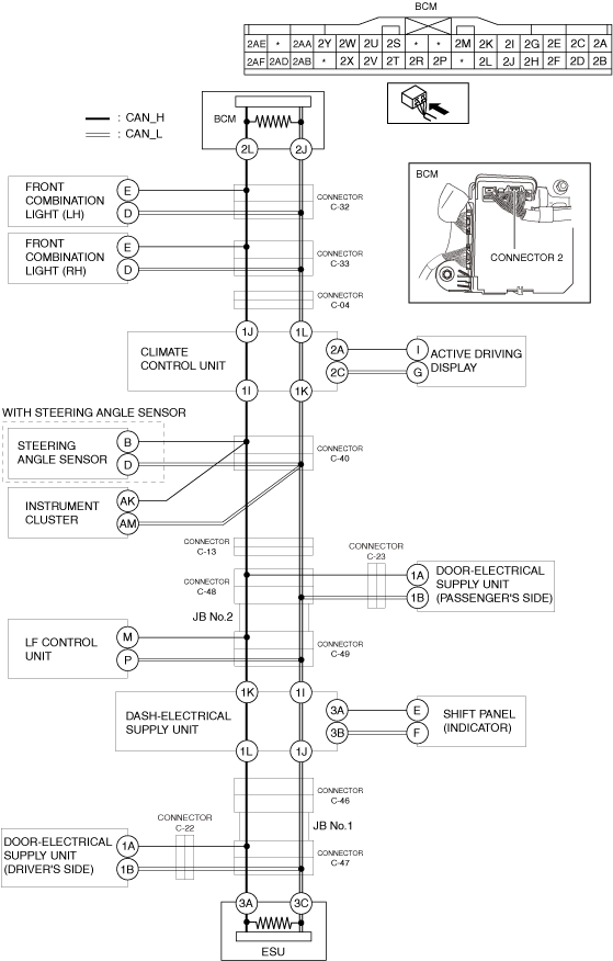
System Wiring Diagram
am3zzw00027514
|
Determination Procedure
-
Caution
-
• When disconnecting the connector, verify that there is no looseness, damage, deformation, corrosion, or poor connection of the connector terminals.• When inspecting the connector, touch it with a paper clip or similar thin pin without directly inserting a tester probe into the terminal.• Disconnect the negative battery terminal before performing any work that requires handling of connectors.
|
Step |
Inspection |
Action |
|
|---|---|---|---|
|
1
|
INSPECT CAN LINE BETWEEN BODY CONTROL MODULE (BCM) AND CONNECTOR C-32 FOR SHORT TO POWER SUPPLY
• Switch the ignition off.
• Disconnect the negative battery terminal. (See NEGATIVE BATTERY TERMINAL DISCONNECTION/CONNECTION [(US)].)
• Disconnect the connector C-32.
• Connect the negative battery terminal. (See NEGATIVE BATTERY TERMINAL DISCONNECTION/CONNECTION [(US)].)
• Switch the ignition ON (engine off).
• Measure the voltage at body control module (BCM) terminals 2L and 2J.
• Is the voltage between 1.5—3.5 V?
|
Yes
|
Go to Step 3.
|
|
No
|
Go to the next step.
|
||
|
2
|
INSPECT BODY CONTROL MODULE (BCM) FOR SHORT TO POWER SUPPLY
• Switch the ignition off.
• Disconnect the negative battery terminal. (See NEGATIVE BATTERY TERMINAL DISCONNECTION/CONNECTION [(US)].)
• Disconnect the connector 2 which has body control module (BCM) terminals 2L and 2J.
• Connect the connector C-32.
• Connect the negative battery terminal. (See NEGATIVE BATTERY TERMINAL DISCONNECTION/CONNECTION [(US)].)
• Switch the ignition ON (engine off).
• Measure the voltage at body control module (BCM) terminals 2L and 2J (wiring harness side).
• Is the voltage between 1.5—3.5 V?
|
Yes
|
Replace the body control module (BCM) because there is a short to the power supply in the body control module (BCM).
|
|
No
|
Repair or replace the wiring harness between the body control module (BCM) and connector C-32 because the wiring harness is shorted to the power supply.
|
||
|
3
|
INSPECT CAN LINE BETWEEN FRONT COMBINATION LIGHT (LH) AND CONNECTOR C-32 FOR SHORT TO POWER SUPPLY
• Measure the voltage at front combination light (LH) terminals E and D.
• Is the voltage between 1.5—3.5 V?
|
Yes
|
Go to Step 5.
|
|
No
|
Go to the next step.
|
||
|
4
|
INSPECT FRONT COMBINATION LIGHT (LH) FOR SHORT TO POWER SUPPLY
• Switch the ignition off.
• Disconnect the negative battery terminal. (See NEGATIVE BATTERY TERMINAL DISCONNECTION/CONNECTION [(US)].)
• Disconnect the front combination light (LH) connector.
• Connect the connector C-32.
• Connect the negative battery terminal. (See NEGATIVE BATTERY TERMINAL DISCONNECTION/CONNECTION [(US)].)
• Switch the ignition ON (engine off).
• Measure the voltage at body control module (BCM) terminals 2L and 2J.
• Is the voltage between 1.5—3.5 V?
|
Yes
|
Replace the front combination light (LH) because there is a short to the power supply in the front combination light (LH).
|
|
No
|
Repair or replace the wiring harness between the front combination light (LH) and connector C-32 because the wiring harness is shorted to the power supply.
|
||
|
5
|
INSPECT CAN LINE BETWEEN CONNECTOR C-33 AND CONNECTOR C-32 FOR SHORT TO POWER SUPPLY
• Switch the ignition off.
• Disconnect the negative battery terminal. (See NEGATIVE BATTERY TERMINAL DISCONNECTION/CONNECTION [(US)].)
• Disconnect the connector C-33.
• Connect the connector C-32.
• Connect the negative battery terminal. (See NEGATIVE BATTERY TERMINAL DISCONNECTION/CONNECTION [(US)].)
• Switch the ignition ON (engine off).
• Measure the voltage at body control module (BCM) terminals 2L and 2J.
• Is the voltage between 1.5—3.5 V?
|
Yes
|
Go to the next step.
|
|
No
|
Repair or replace the wiring harness between connector C-33 and connector C-32 because the wiring harness is shorted to the power supply.
|
||
|
6
|
INSPECT CAN LINE BETWEEN FRONT COMBINATION LIGHT (RH) AND CONNECTOR C-33 FOR SHORT TO POWER SUPPLY
• Measure the voltage at front combination light (RH) terminals E and D.
• Is the voltage between 1.5—3.5 V?
|
Yes
|
Go to Step 8.
|
|
No
|
Go to the next step.
|
||
|
7
|
INSPECT FRONT COMBINATION LIGHT (RH) FOR SHORT TO POWER SUPPLY
• Switch the ignition off.
• Disconnect the negative battery terminal. (See NEGATIVE BATTERY TERMINAL DISCONNECTION/CONNECTION [(US)].)
• Disconnect the front combination light (RH) connector.
• Connect the connector C-33.
• Connect the negative battery terminal. (See NEGATIVE BATTERY TERMINAL DISCONNECTION/CONNECTION [(US)].)
• Switch the ignition ON (engine off).
• Measure the voltage at body control module (BCM) terminals 2L and 2J.
• Is the voltage between 1.5—3.5 V?
|
Yes
|
Replace the front combination light (RH) because there is a short to the power supply in the front combination light (RH).
|
|
No
|
Repair or replace the wiring harness between the front combination light (RH) and connector C-33 because the wiring harness is shorted to the power supply.
|
||
|
8
|
INSPECT CAN LINE BETWEEN CONNECTOR C-04 AND CONNECTOR C-33 FOR SHORT TO POWER SUPPLY
• Switch the ignition off.
• Disconnect the negative battery terminal. (See NEGATIVE BATTERY TERMINAL DISCONNECTION/CONNECTION [(US)].)
• Disconnect the connector C-04.
• Connect the connector C-33.
• Connect the negative battery terminal. (See NEGATIVE BATTERY TERMINAL DISCONNECTION/CONNECTION [(US)].)
• Switch the ignition ON (engine off).
• Measure the voltage at body control module (BCM) terminals 2L and 2J.
• Is the voltage between 1.5—3.5 V?
|
Yes
|
Go to the next step.
|
|
No
|
Repair or replace the wiring harness between connector C-04 and connector C-33 because the wiring harness is shorted to the power supply.
|
||
|
9
|
INSPECT CAN LINE BETWEEN CLIMATE CONTROL UNIT AND CONNECTOR C-04 FOR SHORT TO POWER SUPPLY
• Switch the ignition off.
• Disconnect the negative battery terminal. (See NEGATIVE BATTERY TERMINAL DISCONNECTION/CONNECTION [(US)].)
• Disconnect the climate control unit connector.
• Connect the connector C-04.
• Connect the negative battery terminal. (See NEGATIVE BATTERY TERMINAL DISCONNECTION/CONNECTION [(US)].)
• Switch the ignition ON (engine off).
• Measure the voltage at body control module (BCM) terminals 2L and 2J.
• Is the voltage between 1.5—3.5 V?
|
Yes
|
Go to the next step.
|
|
No
|
Repair or replace the wiring harness between the climate control unit and connector C-04 because the wiring harness is shorted to the power supply.
|
||
|
10
|
INSPECT CAN LINE BETWEEN CLIMATE CONTROL UNIT AND ACTIVE DRIVING DISPLAY FOR SHORT TO POWER SUPPLY
• Measure the voltage at active driving display terminals I and G.
• Is the voltage between 1.5—3.5 V?
|
Yes
|
Go to Step 12.
|
|
No
|
Go to the next step.
|
||
|
11
|
INSPECT ACTIVE DRIVING DISPLAY FOR SHORT TO POWER SUPPLY
• Switch the ignition off.
• Disconnect the negative battery terminal. (See NEGATIVE BATTERY TERMINAL DISCONNECTION/CONNECTION [(US)].)
• Disconnect the active driving display connector.
• Connect the climate control unit connector.
• Connect the negative battery terminal. (See NEGATIVE BATTERY TERMINAL DISCONNECTION/CONNECTION [(US)].)
• Switch the ignition ON (engine off).
• Measure the voltage at body control module (BCM) terminals 2L and 2J.
• Is the voltage between 1.5—3.5 V?
|
Yes
|
Replace the active driving display because there is a short to the power supply in the active driving display.
|
|
No
|
Repair or replace the wiring harness between the active driving display and climate control unit because the wiring harness is shorted to the power supply.
|
||
|
12
|
INSPECT CAN LINE BETWEEN CLIMATE CONTROL UNIT AND ESU FOR SHORT TO POWER SUPPLY
• Measure the voltage at ESU terminals 3A and 3C.
• Is the voltage between 1.5—3.5 V?
|
Yes
|
Replace the climate control unit because there is a short to the power supply in the climate control unit.
|
|
No
|
Go to the next step.
|
||
|
13
|
INSPECT CAN LINE BETWEEN CONNECTOR C-40 AND CLIMATE CONTROL UNIT FOR SHORT TO POWER SUPPLY
• Switch the ignition off.
• Disconnect the negative battery terminal. (See NEGATIVE BATTERY TERMINAL DISCONNECTION/CONNECTION [(US)].)
• Disconnect the connector C-40.
• Connect the climate control unit connector.
• Connect the negative battery terminal. (See NEGATIVE BATTERY TERMINAL DISCONNECTION/CONNECTION [(US)].)
• Switch the ignition ON (engine off).
• Measure the voltage at body control module (BCM) terminals 2L and 2J.
• Is the voltage between 1.5—3.5 V?
|
Yes
|
Go to the next step.
|
|
No
|
Repair or replace the wiring harness between connector C-40 and climate control unit because the wiring harness is shorted to the power supply.
|
||
|
14
|
INSPECT CAN LINE BETWEEN STEERING ANGLE SENSOR AND CONNECTOR C-40 FOR SHORT TO POWER SUPPLY
• Measure the voltage at steering angle sensor terminals B and D.
• Is the voltage between 1.5—3.5 V?
|
Yes
|
Go to Step 16.
|
|
No
|
Go to the next step.
|
||
|
15
|
INSPECT STEERING ANGLE SENSOR FOR SHORT TO POWER SUPPLY
• Switch the ignition off.
• Disconnect the negative battery terminal. (See NEGATIVE BATTERY TERMINAL DISCONNECTION/CONNECTION [(US)].)
• Disconnect the steering angle sensor connector.
• Connect the connector C-40.
• Connect the negative battery terminal. (See NEGATIVE BATTERY TERMINAL DISCONNECTION/CONNECTION [(US)].)
• Switch the ignition ON (engine off).
• Measure the voltage at body control module (BCM) terminals 2L and 2J.
• Is the voltage between 1.5—3.5 V?
|
Yes
|
Replace the steering angle sensor because there is a short to the power supply in the steering angle sensor.
|
|
No
|
Repair or replace the wiring harness between the steering angle sensor and connector C-40 because the wiring harness is shorted to the power supply.
|
||
|
16
|
INSPECT CAN LINE BETWEEN INSTRUMENT CLUSTER AND CONNECTOR C-40 FOR SHORT TO POWER SUPPLY
• Measure the voltage at instrument cluster terminals AK and AM.
• Is the voltage between 1.5—3.5 V?
|
Yes
|
Go to Step 18.
|
|
No
|
Go to the next step.
|
||
|
17
|
INSPECT INSTRUMENT CLUSTER FOR SHORT TO POWER SUPPLY
• Switch the ignition off.
• Disconnect the negative battery terminal. (See NEGATIVE BATTERY TERMINAL DISCONNECTION/CONNECTION [(US)].)
• Disconnect the instrument cluster connector.
• Connect the connector C-40.
• Connect the negative battery terminal. (See NEGATIVE BATTERY TERMINAL DISCONNECTION/CONNECTION [(US)].)
• Switch the ignition ON (engine off).
• Measure the voltage at body control module (BCM) terminals 2L and 2J.
• Is the voltage between 1.5—3.5 V?
|
Yes
|
Replace the instrument cluster because there is a short to the power supply in the instrument cluster.
|
|
No
|
Repair or replace the wiring harness between the instrument cluster and connector C-40 because the wiring harness is shorted to the power supply.
|
||
|
18
|
INSPECT CAN LINE BETWEEN CONNECTOR C-13 AND CONNECTOR C-40 FOR SHORT TO POWER SUPPLY
• Switch the ignition off.
• Disconnect the negative battery terminal. (See NEGATIVE BATTERY TERMINAL DISCONNECTION/CONNECTION [(US)].)
• Disconnect the connector C-13.
• Connect the connector C-40.
• Connect the negative battery terminal. (See NEGATIVE BATTERY TERMINAL DISCONNECTION/CONNECTION [(US)].)
• Switch the ignition ON (engine off).
• Measure the voltage at body control module (BCM) terminals 2L and 2J.
• Is the voltage between 1.5—3.5 V?
|
Yes
|
Go to the next step.
|
|
No
|
Repair or replace the wiring harness between connector C-13 and connector C-40 because the wiring harness is shorted to the power supply.
|
||
|
19
|
INSPECT CAN LINE BETWEEN CONNECTOR C-48 AND CONNECTOR C-13 FOR SHORT TO POWER SUPPLY
• Switch the ignition off.
• Disconnect the negative battery terminal. (See NEGATIVE BATTERY TERMINAL DISCONNECTION/CONNECTION [(US)].)
• Disconnect the connector C-48.
• Connect the connector C-13.
• Connect the negative battery terminal. (See NEGATIVE BATTERY TERMINAL DISCONNECTION/CONNECTION [(US)].)
• Switch the ignition ON (engine off).
• Measure the voltage at body control module (BCM) terminals 2L and 2J.
• Is the voltage between 1.5—3.5 V?
|
Yes
|
Go to the next step.
|
|
No
|
Repair or replace the wiring harness between connector C-48 and connector C-13 because the wiring harness is shorted to the power supply.
|
||
|
20
|
INSPECT CAN LINE BETWEEN DOOR-ELECTRICAL SUPPLY UNIT (PASSENGER’S SIDE) AND CONNECTOR C-48 FOR SHORT TO POWER SUPPLY
• Measure the voltage at door-electrical supply unit (passenger’s side) terminals 1A and 1B.
• Is the voltage between 1.5—3.5 V?
|
Yes
|
Go to Step 23.
|
|
No
|
Go to the next step.
|
||
|
21
|
INSPECT CAN LINE BETWEEN DOOR-ELECTRICAL SUPPLY UNIT (PASSENGER’S SIDE) AND CONNECTOR C-23 FOR SHORT TO POWER SUPPLY
• Switch the ignition off.
• Disconnect the negative battery terminal. (See NEGATIVE BATTERY TERMINAL DISCONNECTION/CONNECTION [(US)].)
• Disconnect the connector C-23.
• Connect the negative battery terminal. (See NEGATIVE BATTERY TERMINAL DISCONNECTION/CONNECTION [(US)].)
• Switch the ignition ON (engine off).
• Measure the voltage at door-electrical supply unit (passenger’s side) terminals 1A and 1B.
• Is the voltage between 1.5—3.5 V?
|
Yes
|
Repair or replace the wiring harness between connector C-48 and connector C-23 because the wiring harness is shorted to the power supply.
|
|
No
|
Go to the next step.
|
||
|
22
|
INSPECT DOOR-ELECTRICAL SUPPLY UNIT (PASSENGER’S SIDE) FOR SHORT TO POWER SUPPLY
• Switch the ignition off.
• Disconnect the negative battery terminal. (See NEGATIVE BATTERY TERMINAL DISCONNECTION/CONNECTION [(US)].)
• Disconnect the door-electrical supply unit (passenger’s side) connector.
• Connect the connector C-23.
• Connect the connector C-48.
• Connect the negative battery terminal. (See NEGATIVE BATTERY TERMINAL DISCONNECTION/CONNECTION [(US)].)
• Switch the ignition ON (engine off).
• Measure the voltage at body control module (BCM) terminals 2L and 2J.
• Is the voltage between 1.5—3.5 V?
|
Yes
|
Replace the door-electrical supply unit (passenger’s side) because there is a short to the power supply in the door-electrical supply unit (passenger’s side).
|
|
No
|
Repair or replace the wiring harness between the door-electrical supply unit (passenger’s side) and connector C-23 because the wiring harness is shorted to the power supply.
|
||
|
23
|
INSPECT JB No.2 FOR SHORT TO POWER SUPPLY
• Switch the ignition off.
• Disconnect the negative battery terminal. (See NEGATIVE BATTERY TERMINAL DISCONNECTION/CONNECTION [(US)].)
• Disconnect the connector C-49.
• Connect the connector C-48.
• Connect the negative battery terminal. (See NEGATIVE BATTERY TERMINAL DISCONNECTION/CONNECTION [(US)].)
• Switch the ignition ON (engine off).
• Measure the voltage at body control module (BCM) terminals 2L and 2J.
• Is the voltage between 1.5—3.5 V?
|
Yes
|
Go to the next step.
|
|
No
|
Replace the JB No.2 because there is a short to the power supply in the JB No.2.
|
||
|
24
|
INSPECT CAN LINE BETWEEN LF CONTROL UNIT AND CONNECTOR C-49 FOR SHORT TO POWER SUPPLY
• Measure the voltage at LF control unit terminals M and P.
• Is the voltage between 1.5—3.5 V?
|
Yes
|
Go to Step 26.
|
|
No
|
Go to the next step.
|
||
|
25
|
INSPECT LF CONTROL UNIT FOR SHORT TO POWER SUPPLY
• Switch the ignition off.
• Disconnect the negative battery terminal. (See NEGATIVE BATTERY TERMINAL DISCONNECTION/CONNECTION [(US)].)
• Disconnect the LF control unit connector.
• Connect the connector C-49.
• Connect the negative battery terminal. (See NEGATIVE BATTERY TERMINAL DISCONNECTION/CONNECTION [(US)].)
• Switch the ignition ON (engine off).
• Measure the voltage at body control module (BCM) terminals 2L and 2J.
• Is the voltage between 1.5—3.5 V?
|
Yes
|
Replace the LF control unit because there is a short to the power supply in the LF control unit.
|
|
No
|
Repair or replace the wiring harness between the LF control unit and connector C-49 because the wiring harness is shorted to the power supply.
|
||
|
26
|
INSPECT CAN LINE BETWEEN DASH-ELECTRICAL SUPPLY UNIT AND CONNECTOR C-49 FOR SHORT TO POWER SUPPLY
• Switch the ignition off.
• Disconnect the negative battery terminal. (See NEGATIVE BATTERY TERMINAL DISCONNECTION/CONNECTION [(US)].)
• Disconnect the dash-electrical supply unit connector.
• Connect the connector C-49.
• Connect the negative battery terminal. (See NEGATIVE BATTERY TERMINAL DISCONNECTION/CONNECTION [(US)].)
• Switch the ignition ON (engine off).
• Measure the voltage at body control module (BCM) terminals 2L and 2J.
• Is the voltage between 1.5—3.5 V?
|
Yes
|
Go to the next step.
|
|
No
|
Repair or replace the wiring harness between the dash-electrical supply unit and connector C-49 because the wiring harness is shorted to the power supply.
|
||
|
27
|
INSPECT CAN LINE BETWEEN SHIFT PANEL (INDICATOR) AND DASH-ELECTRICAL SUPPLY UNIT FOR SHORT TO POWER SUPPLY
• Measure the voltage at shift panel (indicator) terminals E and F.
• Is the voltage between 1.5—3.5 V?
|
Yes
|
Go to Step 29.
|
|
No
|
Go to the next step.
|
||
|
28
|
INSPECT SHIFT PANEL (INDICATOR) FOR SHORT TO POWER SUPPLY
• Switch the ignition off.
• Disconnect the negative battery terminal. (See NEGATIVE BATTERY TERMINAL DISCONNECTION/CONNECTION [(US)].)
• Disconnect the shift panel (indicator) connector.
• Connect the dash-electrical supply unit connector.
• Connect the negative battery terminal. (See NEGATIVE BATTERY TERMINAL DISCONNECTION/CONNECTION [(US)].)
• Switch the ignition ON (engine off).
• Measure the voltage at body control module (BCM) terminals 2L and 2J.
• Is the voltage between 1.5—3.5 V?
|
Yes
|
Replace the shift panel (indicator) because there is a short to the power supply in the shift panel (indicator).
(See INDICATOR INSPECTION.)
|
|
No
|
Repair or replace the wiring harness between the shift panel (indicator) and dash-electrical supply unit because the wiring harness is shorted to the power supply.
|
||
|
29
|
INSPECT CAN LINE BETWEEN ESU AND DASH-ELECTRICAL SUPPLY UNIT FOR SHORT TO POWER SUPPLY
• Measure the voltage at ESU terminals 3A and 3C.
• Is the voltage between 1.5—3.5 V?
|
Yes
|
Replace the dash-electrical supply unit because there is a short to the power supply in the dash-electrical supply unit.
|
|
No
|
Go to the next step.
|
||
|
30
|
INSPECT CAN LINE BETWEEN CONNECTOR C-46 AND DASH-ELECTRICAL SUPPLY UNIT FOR SHORT TO POWER SUPPLY
• Switch the ignition off.
• Disconnect the negative battery terminal. (See NEGATIVE BATTERY TERMINAL DISCONNECTION/CONNECTION [(US)].)
• Disconnect the connector C-46.
• Connect the dash-electrical supply unit connector.
• Connect the negative battery terminal. (See NEGATIVE BATTERY TERMINAL DISCONNECTION/CONNECTION [(US)].)
• Switch the ignition ON (engine off).
• Measure the voltage at body control module (BCM) terminals 2L and 2J.
• Is the voltage between 1.5—3.5 V?
|
Yes
|
Go to the next step.
|
|
No
|
Repair or replace the wiring harness between the dash-electrical supply unit and connector C-46 because the wiring harness is shorted to the power supply.
|
||
|
31
|
INSPECT JB No.1 FOR SHORT TO POWER SUPPLY
• Switch the ignition off.
• Disconnect the negative battery terminal. (See NEGATIVE BATTERY TERMINAL DISCONNECTION/CONNECTION [(US)].)
• Disconnect the connector C-47.
• Connect the connector C-46.
• Connect the negative battery terminal. (See NEGATIVE BATTERY TERMINAL DISCONNECTION/CONNECTION [(US)].)
• Switch the ignition ON (engine off).
• Measure the voltage at body control module (BCM) terminals 2L and 2J.
• Is the voltage between 1.5—3.5 V?
|
Yes
|
Go to the next step.
|
|
No
|
Replace the JB No.1 because there is a short to the power supply in the JB No.1.
|
||
|
32
|
INSPECT CAN LINE BETWEEN DOOR-ELECTRICAL SUPPLY UNIT (DRIVER’S SIDE) AND CONNECTOR C-47 FOR SHORT TO POWER SUPPLY
• Measure the voltage at door-electrical supply unit (driver’s side) terminals 1A and 1B.
• Is the voltage between 1.5—3.5 V?
|
Yes
|
Go to Step 35.
|
|
No
|
Go to the next step.
|
||
|
33
|
INSPECT CAN LINE BETWEEN DOOR-ELECTRICAL SUPPLY UNIT (DRIVER’S SIDE) AND CONNECTOR C-22 FOR SHORT TO POWER SUPPLY
• Switch the ignition off.
• Disconnect the negative battery terminal. (See NEGATIVE BATTERY TERMINAL DISCONNECTION/CONNECTION [(US)].)
• Disconnect the connector C-22.
• Connect the negative battery terminal. (See NEGATIVE BATTERY TERMINAL DISCONNECTION/CONNECTION [(US)].)
• Switch the ignition ON (engine off).
• Measure the voltage at door-electrical supply unit (driver’s side) terminals 1A and 1B.
• Is the voltage between 1.5—3.5 V?
|
Yes
|
Repair or replace the wiring harness between connector C-47 and connector C-22 because the wiring harness is shorted to the power supply.
|
|
No
|
Go to the next step.
|
||
|
34
|
INSPECT DOOR-ELECTRICAL SUPPLY UNIT (DRIVER’S SIDE) FOR SHORT TO POWER SUPPLY
• Switch the ignition off.
• Disconnect the negative battery terminal. (See NEGATIVE BATTERY TERMINAL DISCONNECTION/CONNECTION [(US)].)
• Disconnect the door-electrical supply unit (driver’s side) connector.
• Connect the connector C-22.
• Connect the connector C-47.
• Connect the negative battery terminal. (See NEGATIVE BATTERY TERMINAL DISCONNECTION/CONNECTION [(US)].)
• Switch the ignition ON (engine off).
• Measure the voltage at body control module (BCM) terminals 2L and 2J.
• Is the voltage between 1.5—3.5 V?
|
Yes
|
Replace the door-electrical supply unit (driver’s side) because there is a short to the power supply in the door-electrical supply unit (driver’s side).
|
|
No
|
Repair or replace the wiring harness between the door-electrical supply unit (driver’s side) and connector C-22 because the wiring harness is shorted to the power supply.
|
||
|
35
|
INSPECT ESU FOR SHORT TO POWER SUPPLY
• Switch the ignition off.
• Disconnect the negative battery terminal. (See NEGATIVE BATTERY TERMINAL DISCONNECTION/CONNECTION [(US)].)
• Disconnect the ESU connector.
• Connect the connector C-47.
• Connect the negative battery terminal. (See NEGATIVE BATTERY TERMINAL DISCONNECTION/CONNECTION [(US)].)
• Switch the ignition ON (engine off).
• Measure the voltage at body control module (BCM) terminals 2L and 2J.
• Is the voltage between 1.5—3.5 V?
|
Yes
|
Replace the ESU because there is a short to the power supply in the ESU.
|
|
No
|
Repair or replace the wiring harness between the ESU and connector C-47 because the wiring harness is shorted to the power supply.
|
||