DETERMINING OPEN CIRCUIT LOCATION (CAN-BUS No.3) [(US)]
DETERMINING OPEN CIRCUIT LOCATION (CAN-BUS No.3) [(US)]
SM2566451
id1002x1002500
-
Caution
-
• Perform the following malfunction diagnosis only when it is diagnosed with a open circuit by CONTROLLER AREA NETWORK (CAN) MALFUNCTION DIAGNOSIS FLOW. (See CONTROLLER AREA NETWORK (CAN) MALFUNCTION DIAGNOSIS FLOW [(US)].)• If the malfunctioning part is detected in the communication line, before disconnecting the related connector for inspection, press the connector in the connection direction to verify that there is no looseness or disconnection.• When disconnecting the connector, verify that there is no damage, deformation, or corrosion of the connector terminals.
1.Verify the CAN system-related module DTCs and the module displayed in red or blue on the M-MDS screen.
2.Apply the communication error DTC and the module displayed in red or blue to the DTC output pattern and malfunctioning location, and select the possible cause for the diagnostic result and the reference for the inspection item. (See DTC Output Pattern And Malfunctioning Location)
-
Note
-
• The open circuit location can be determined by the DTC indicated in the DTC output pattern and malfunctioning location chart. DTCs not listed in the chart are not used for the determination of the open circuit location. (See DTC Output Pattern And Malfunctioning Location.)• The module may be displayed in red or blue on the M-MDS screen even if there is no malfunction depending on the vehicle specification.
3.Inspect the possible cause and inspection item of the applicable malfunctioning part.
4.After repairs, return to CONTROLLER AREA NETWORK (CAN) MALFUNCTION DIAGNOSIS FLOW, and verify that the repairs have been completed. (See CONTROLLER AREA NETWORK (CAN) MALFUNCTION DIAGNOSIS FLOW [(US)].)
DTC Output Pattern And Malfunctioning Location
Cross (×): Communication error-related DTC
|
M-MDS display |
DTC |
DTC output pattern and malfunctioning location |
|||||||||||||||||||
|---|---|---|---|---|---|---|---|---|---|---|---|---|---|---|---|---|---|---|---|---|---|
|
DTC output module |
|||||||||||||||||||||
|
PCM
|
U0101:00
|
||||||||||||||||||||
|
U0121:00
|
|||||||||||||||||||||
|
U0131:00
|
|||||||||||||||||||||
|
U0140:00
|
×
|
||||||||||||||||||||
|
U0151:00
|
|||||||||||||||||||||
|
U0155:00
|
×
|
×
|
×
|
×
|
×
|
||||||||||||||||
|
U0164:00
|
×
|
×
|
×
|
×
|
×
|
×
|
×
|
×
|
|||||||||||||
|
U2121:00
|
|||||||||||||||||||||
|
U212E:00
|
×
|
×
|
×
|
×
|
×
|
×
|
×
|
×
|
×
|
||||||||||||
|
U2131:00
|
×
|
×
|
×
|
×
|
×
|
×
|
×
|
×
|
×
|
||||||||||||
|
U2133:00
|
×
|
×
|
×
|
×
|
|||||||||||||||||
|
Electric parking brake control module / DSC HU/CM
|
U0100:00
|
||||||||||||||||||||
|
U0101:00
|
|||||||||||||||||||||
|
U0131:00
|
|||||||||||||||||||||
|
U0140:00
|
×
|
||||||||||||||||||||
|
U0151:00
|
|||||||||||||||||||||
|
U0155:00
|
×
|
×
|
×
|
×
|
×
|
||||||||||||||||
|
U0164:00
|
×
|
×
|
×
|
×
|
×
|
×
|
×
|
×
|
|||||||||||||
|
U2121:00
|
|||||||||||||||||||||
|
U212E:00
|
×
|
×
|
×
|
×
|
×
|
×
|
×
|
×
|
×
|
||||||||||||
|
U2131:00
|
×
|
×
|
×
|
×
|
×
|
×
|
×
|
×
|
×
|
||||||||||||
|
EPS control module
|
U0100:00
|
||||||||||||||||||||
|
U0121:00
|
|||||||||||||||||||||
|
U0140:00
|
×
|
||||||||||||||||||||
|
U2121:00
|
|||||||||||||||||||||
|
Vehicle control module (VCM)
|
U0100:00
|
||||||||||||||||||||
|
U0101:00
|
|||||||||||||||||||||
|
U0121:00
|
|||||||||||||||||||||
|
U0126:00
|
×
|
×
|
×
|
×
|
×
|
||||||||||||||||
|
U0131:00
|
|||||||||||||||||||||
|
U0140:00
|
×
|
||||||||||||||||||||
|
U0151:00
|
|||||||||||||||||||||
|
U0155:00
|
×
|
×
|
×
|
×
|
×
|
||||||||||||||||
|
U0156:00
|
|||||||||||||||||||||
|
U0164:00
|
×
|
×
|
×
|
×
|
×
|
×
|
×
|
×
|
|||||||||||||
|
U2120:00
|
|||||||||||||||||||||
|
U2122:00
|
|||||||||||||||||||||
|
U2123:00
|
|||||||||||||||||||||
|
U2125:00
|
|||||||||||||||||||||
|
U2126:00
|
|||||||||||||||||||||
|
U212E:00
|
×
|
×
|
×
|
×
|
×
|
×
|
×
|
×
|
×
|
||||||||||||
|
U2131:00
|
×
|
×
|
×
|
×
|
×
|
×
|
×
|
×
|
×
|
||||||||||||
|
U2132:00
|
|||||||||||||||||||||
|
U2133:00
|
×
|
×
|
×
|
×
|
|||||||||||||||||
|
U2139:00
|
|||||||||||||||||||||
|
U213A:00
|
×
|
×
|
×
|
×
|
×
|
×
|
|||||||||||||||
|
Body control module (BCM)
|
U0100:00
|
||||||||||||||||||||
|
U0101:00
|
|||||||||||||||||||||
|
U0115:00
|
|||||||||||||||||||||
|
U0121:00
|
|||||||||||||||||||||
|
U0121:87
|
|||||||||||||||||||||
|
U0126:00
|
×
|
×
|
×
|
×
|
×
|
||||||||||||||||
|
U0131:00
|
|||||||||||||||||||||
|
U0151:00
|
|||||||||||||||||||||
|
U0155:00
|
×
|
×
|
×
|
×
|
×
|
||||||||||||||||
|
U0156:00
|
|||||||||||||||||||||
|
U0158:00
|
×
|
×
|
×
|
×
|
|||||||||||||||||
|
U0164:00
|
×
|
×
|
×
|
×
|
×
|
×
|
×
|
×
|
|||||||||||||
|
U0182:00
|
|||||||||||||||||||||
|
U2121:49
|
|||||||||||||||||||||
|
U212A:00
|
×
|
×
|
|||||||||||||||||||
|
U212C:00
|
×
|
×
|
×
|
×
|
×
|
×
|
×
|
×
|
|||||||||||||
|
U212D:00
|
×
|
×
|
×
|
||||||||||||||||||
|
U212E:00
|
×
|
×
|
×
|
×
|
×
|
×
|
×
|
×
|
×
|
||||||||||||
|
U2131:00
|
×
|
×
|
×
|
×
|
×
|
×
|
×
|
×
|
×
|
||||||||||||
|
U2133:00
|
×
|
×
|
×
|
×
|
|||||||||||||||||
|
U213A:00
|
×
|
×
|
×
|
×
|
×
|
×
|
|||||||||||||||
|
U213B:00
|
×
|
×
|
×
|
×
|
×
|
×
|
×
|
||||||||||||||
|
Connectivity master unit (CMU)
|
U0140:00
|
×
|
|||||||||||||||||||
|
Telematics communication unit
|
U0140:00
|
×
|
|||||||||||||||||||
|
U0151:00
|
|||||||||||||||||||||
|
U0164:00
|
×
|
×
|
×
|
×
|
×
|
×
|
×
|
×
|
|||||||||||||
|
U213C:00
|
|||||||||||||||||||||
|
Adaptive front lighting system (AFS) control module
|
U0122:87
|
||||||||||||||||||||
|
U0126:87
|
×
|
×
|
×
|
×
|
×
|
||||||||||||||||
|
U212A:87
|
×
|
×
|
|||||||||||||||||||
|
U212B:87
|
×
|
||||||||||||||||||||
|
U212D:87
|
×
|
×
|
×
|
||||||||||||||||||
|
Dash-electrical supply unit
|
U0100:00
|
||||||||||||||||||||
|
U0101:00
|
|||||||||||||||||||||
|
U0121:00
|
|||||||||||||||||||||
|
U0151:00
|
|||||||||||||||||||||
|
U212B:00
|
|||||||||||||||||||||
|
U212E:00
|
×
|
×
|
|||||||||||||||||||
|
U2131:00
|
×
|
×
|
|||||||||||||||||||
|
U2133:00
|
×
|
||||||||||||||||||||
|
U213A:00
|
×
|
||||||||||||||||||||
|
SAS control module
|
U0140:00
|
×
|
|||||||||||||||||||
|
U0155:00
|
×
|
×
|
×
|
×
|
×
|
||||||||||||||||
|
U0156:00
|
×
|
×
|
×
|
×
|
×
|
||||||||||||||||
|
TCM
|
U0100:00
|
||||||||||||||||||||
|
U0121:00
|
|||||||||||||||||||||
|
U0131:00
|
|||||||||||||||||||||
|
U0140:00
|
×
|
||||||||||||||||||||
|
U0155:00
|
×
|
×
|
×
|
×
|
×
|
||||||||||||||||
|
U212C:00
|
×
|
×
|
×
|
×
|
×
|
×
|
×
|
×
|
|||||||||||||
|
M-MDS display module
|
Module displayed in red or blue
|
||||||||||||||||||||
|
ESU
|
×
|
×
|
×
|
×
|
×
|
×
|
×
|
×
|
×
|
||||||||||||
|
Door-electrical supply unit (driver’s side)
|
×
|
×
|
×
|
×
|
×
|
×
|
×
|
×
|
×
|
||||||||||||
|
Shift panel (indicator)
|
×
|
×
|
×
|
×
|
×
|
×
|
×
|
×
|
|||||||||||||
|
Dash-electrical supply unit
|
×
|
×
|
×
|
×
|
×
|
×
|
×
|
×
|
|||||||||||||
|
LF control unit
|
×
|
×
|
×
|
×
|
×
|
×
|
×
|
||||||||||||||
|
Door-electrical supply unit (passenger’s side)
|
×
|
×
|
×
|
×
|
×
|
×
|
|||||||||||||||
|
Instrument cluster
|
×
|
×
|
×
|
×
|
×
|
||||||||||||||||
|
Steering angle sensor
|
×
|
×
|
×
|
×
|
×
|
||||||||||||||||
|
Active driving display
|
×
|
×
|
×
|
×
|
|||||||||||||||||
|
Climate control unit
|
×
|
×
|
×
|
×
|
|||||||||||||||||
|
Front combination light (RH)
|
×
|
×
|
×
|
||||||||||||||||||
|
Front combination light (LH)
|
×
|
×
|
|||||||||||||||||||
|
Diagnostic result
|
|||||||||||||||||||||
|
Possible cause and inspection item
|
|||||||||||||||||||||
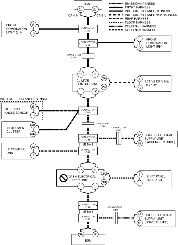
A
Possible cause
-
• Connector terminal disconnection, poor contact, damage, deformation, corrosion• Electrical supply unit (ESU) power supply voltage or body ground malfunction• Open circuit in wiring harness between electrical supply unit (ESU) and connector C-47• Connector C-47 malfunction• Electrical supply unit (ESU) malfunction
System wiring diagram
am3zzw00027546
|
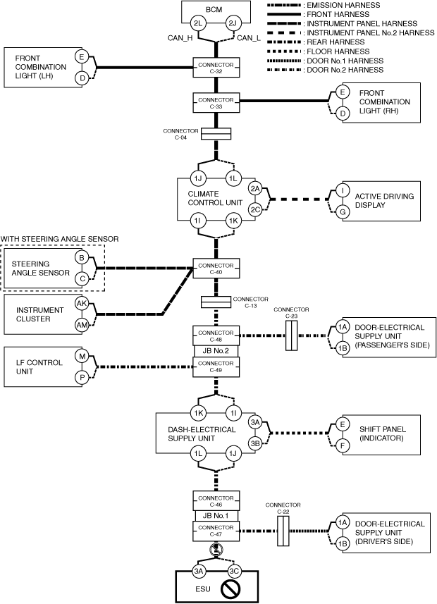
Inspection item
-
• Electrical supply unit (ESU) power supply voltage-related wiring harness and fuse• Electrical supply unit (ESU) body ground related wiring harness• Electrical supply unit (ESU) connector• Connector C-47• Wiring harness between electrical supply unit (ESU) terminal 3A and connector C-47• Wiring harness between electrical supply unit (ESU) terminal 3C and connector C-47• Electrical supply unit (ESU)
B
Possible cause
-
• Connector terminal disconnection, poor contact, damage, deformation, corrosion• Door-electrical supply unit (driver’s side) power supply voltage or body ground malfunction• Open circuit in wiring harness between door-electrical supply unit (driver’s side) and connector C-22• Open circuit in wiring harness between connector C-22 and connector C-47• Connector C-22 malfunction• Connector C-47 malfunction• Door-electrical supply unit (driver’s side) malfunction
System wiring diagram
am3zzw00027547
|
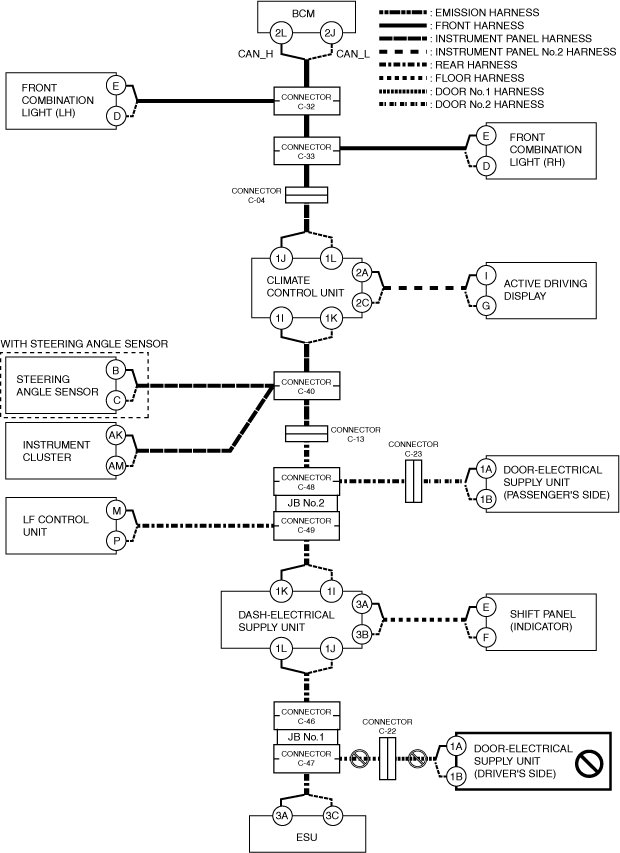
Inspection item
-
• Door-electrical supply unit (driver’s side) power supply voltage-related wiring harness and fuse• Door-electrical supply unit (driver’s side) body ground related wiring harness• Door-electrical supply unit (driver’s side) connector• Connector C-22• Connector C-47• Wiring harness between connector C-22 and connector C-47• Wiring harness between door-electrical supply unit (driver’s side) terminal 1A and connector C-22• Wiring harness between door-electrical supply unit (driver’s side) terminal 1B and connector C-22• Door-electrical supply unit (driver’s side)
C
Possible cause
-
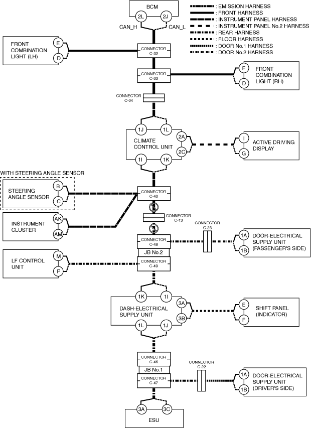
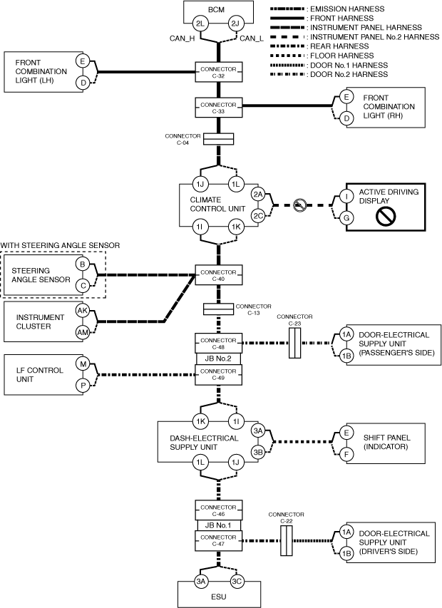
• Connector terminal disconnection, poor contact, damage, deformation, corrosion• Open circuit in wiring harness between connector C-46 and dash-electrical supply unit• Connector C-46 malfunction• JB No.1 malfunction• CAN circuit in dash-electrical supply unit malfunction
System wiring diagram
am3zzw00027548
|
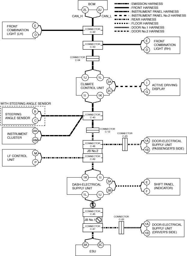
Inspection item
-
• Dash-electrical supply unit connector• Connector C-46• Wiring harness between dash-electrical supply unit terminal 1L and connector C-46• Wiring harness between dash-electrical supply unit terminal 1J and connector C-46• JB No.1• Dash-electrical supply unit
-
― Between dash-electrical supply unit terminal 1L and dash-electrical supply unit terminal 1K― Between dash-electrical supply unit terminal 1J and dash-electrical supply unit terminal 1I
-
D
Possible cause
-
• Connector terminal disconnection, poor contact, damage, deformation, corrosion• Shift panel (indicator) power supply voltage or body ground malfunction• Open circuit in wiring harness between shift panel (indicator) and dash-electrical supply unit• Shift panel (indicator) malfunction
System wiring diagram
am3zzw00027549
|
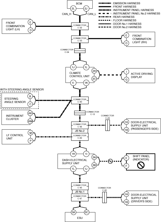
Inspection item
-
• Shift panel (indicator) power supply voltage-related wiring harness and fuse• Shift panel (indicator) body ground related wiring harness• Shift panel (indicator) connector• Wiring harness between shift panel (indicator) terminal E and dash-electrical supply unit terminal 3A• Wiring harness between shift panel (indicator) terminal F and dash-electrical supply unit terminal 3B• Shift panel (indicator)
E
Possible cause
-
• Connector terminal disconnection, poor contact, damage, deformation, corrosion• Dash-electrical supply unit power supply voltage or body ground malfunction• Dash-electrical supply unit malfunction
System wiring diagram
am3zzw00027550
|
Inspection item
-
• Dash-electrical supply unit power supply voltage-related wiring harness and fuse• Dash-electrical supply unit body ground related wiring harness• Dash-electrical supply unit
F
Possible cause
-
• Connector terminal disconnection, poor contact, damage, deformation, corrosion• Open circuit in wiring harness between connector C-49 and dash-electrical supply unit• Connector C-49 malfunction• CAN circuit in dash-electrical supply unit malfunction
System wiring diagram
am3zzw00027551
|
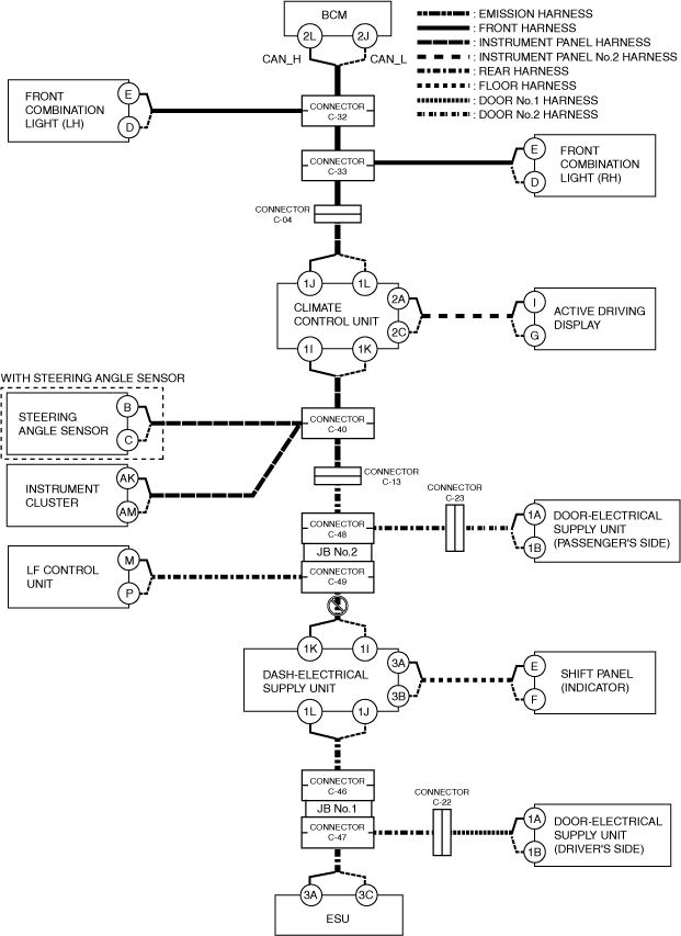
Inspection item
-
• Dash-electrical supply unit connector• Connector C-49• Wiring harness between dash-electrical supply unit terminal 1L and connector C-49• Wiring harness between dash-electrical supply unit terminal 1J and connector C-49• Dash-electrical supply unit
-
― Between dash-electrical supply unit terminal 1L and dash-electrical supply unit terminal 1K― Between dash-electrical supply unit terminal 1J and dash-electrical supply unit terminal 1I
-
G
Possible cause
-
• Connector terminal disconnection, poor contact, damage, deformation, corrosion• LF control unit power supply voltage or body ground malfunction• Open circuit in wiring harness between LF control unit and connector C-49• Connector C-49 malfunction• LF control unit malfunction
System wiring diagram
am3zzw00027552
|
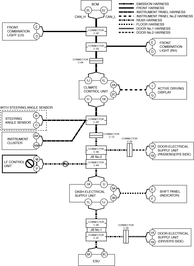
Inspection item
-
• LF control unit power supply voltage-related wiring harness and fuse• LF control unit body ground related wiring harness• LF control unit connector• Connector C-49• Wiring harness between LF control unit terminal M and connector C-49• Wiring harness between LF control unit terminal P and connector C-49• LF control unit
H
Possible cause
-
• Connector terminal disconnection, poor contact, damage, deformation, corrosion• Open circuit in wiring harness between connector C-49 and connector C-48• Connector C-49 malfunction• Connector C-48 malfunction• JB No.2 malfunction
System wiring diagram
am3zzw00027553
|

Inspection item
-
• Connector C-49• Connector C-48• Wiring harness between connector C-49 and connector C-48• JB No.2
I
Possible cause
-
• Connector terminal disconnection, poor contact, damage, deformation, corrosion• Door-electrical supply unit (passenger’s side) power supply voltage or body ground malfunction• Open circuit in wiring harness between door-electrical supply unit (passenger’s side) and connector C-23• Open circuit in wiring harness between connector C-23 and connector C-48• Connector C-23 malfunction• Connector C-48 malfunction• Door-electrical supply unit (passenger’s side) malfunction
System wiring diagram
am3zzw00027554
|
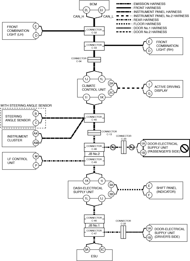
Inspection item
-
• Door-electrical supply unit (passenger’s side) power supply voltage-related wiring harness and fuse• Door-electrical supply unit (passenger’s side) body ground related wiring harness• Door-electrical supply unit (passenger’s side) connector• Connector C-23• Connector C-48• Wiring harness between connector C-23 and connector C-48• Wiring harness between door-electrical supply unit (passenger’s side) terminal 1A and connector C-23• Wiring harness between door-electrical supply unit (passenger’s side) terminal 1B and connector C-23• Door-electrical supply unit (passenger’s side)
J
Possible cause
-
• Connector terminal disconnection, poor contact, damage, deformation, corrosion• Open circuit in wiring harness between connector C-48 and connector C-13• Open circuit in wiring harness between connector C-13 and connector C-40• Connector C-48 malfunction• Connector C-13 malfunction• Connector C-40 malfunction
System wiring diagram
am3zzw00027555
|
Inspection item
-
• Connector C-48• Connector C-13• Connector C-40• Wiring harness between connector C-48 and connector C-13• Wiring harness between connector C-13 and connector C-40
K
Possible cause
-
• Connector terminal disconnection, poor contact, damage, deformation, corrosion• Instrument cluster power supply voltage or body ground malfunction• Open circuit in wiring harness between instrument cluster and connector C-40• Connector C-40 malfunction• Instrument cluster malfunction
System wiring diagram
am3zzw00027556
|
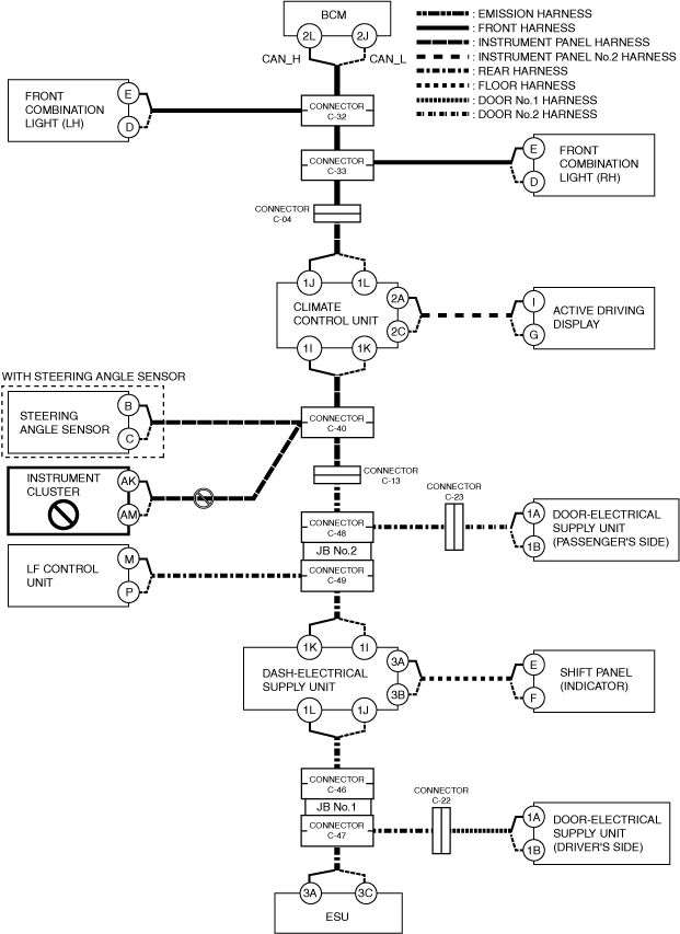
Inspection item
-
• Instrument cluster power supply voltage-related wiring harness and fuse• Instrument cluster body ground related wiring harness• Instrument cluster connector• Connector C-40• Wiring harness between instrument cluster terminal AK and connector C-40• Wiring harness between instrument cluster terminal AM and connector C-40• Instrument cluster
L
Possible cause
-
• Connector terminal disconnection, poor contact, damage, deformation, corrosion• Steering angle sensor power supply voltage or body ground malfunction• Open circuit in wiring harness between steering angle sensor and connector C-40• Connector C-40 malfunction• Steering angle sensor malfunction
System wiring diagram
am3zzw00027557
|
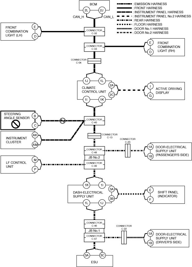
Inspection item
-
• Steering angle sensor power supply voltage-related wiring harness and fuse• Steering angle sensor body ground related wiring harness• Steering angle sensor connector• Connector C-40• Wiring harness between steering angle sensor terminal B and connector C-40• Wiring harness between steering angle sensor terminal C and connector C-40• Steering angle sensor
M
Possible cause
-
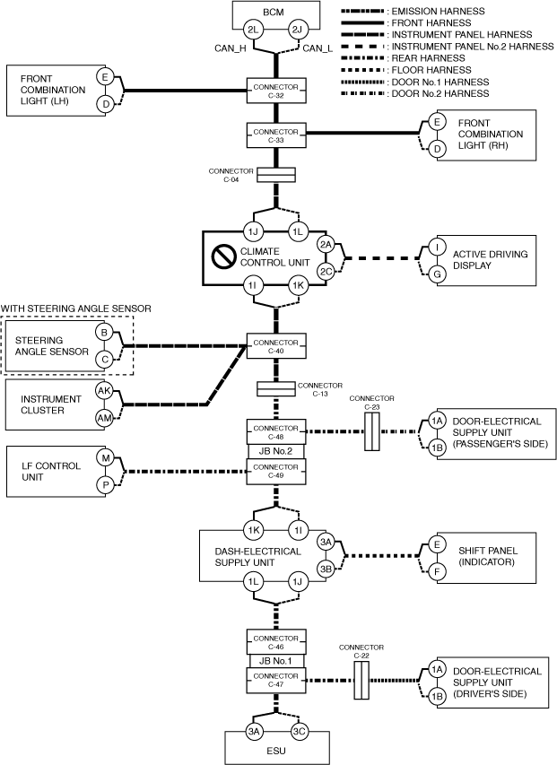
• Connector terminal disconnection, poor contact, damage, deformation, corrosion• Open circuit in wiring harness between climate control unit and connector C-40• Connector C-40 malfunction• CAN circuit in climate control unit malfunction
System wiring diagram
am3zzw00027558
|
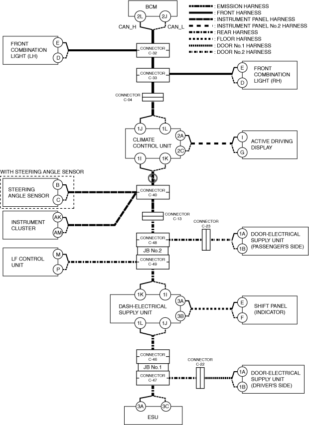
Inspection item
-
• Connector C-40• Wiring harness between climate control unit terminal 1I and connector C-40• Wiring harness between climate control unit terminal 1K and connector C-40• Climate control unit
-
― Between climate control unit terminal 1I and climate control unit terminal 1J― Between climate control unit terminal 1K and climate control unit terminal 1L
-
N
Possible cause
-
• Connector terminal disconnection, poor contact, damage, deformation, corrosion• Active driving display power supply voltage or body ground malfunction• Open circuit in wiring harness between active driving display and climate control unit• Active driving display malfunction
System wiring diagram
am3zzw00027559
|
Inspection item
-
• Active driving display power supply voltage-related wiring harness and fuse• Active driving display body ground related wiring harness• Active driving display connector• Wiring harness between active driving display terminal I and climate control unit terminal 2A• Wiring harness between active driving display terminal G and climate control unit terminal 2C• Active driving display
O
Possible cause
-
• Connector terminal disconnection, poor contact, damage, deformation, corrosion• Climate control unit power supply voltage or body ground malfunction• Climate control unit malfunction
System wiring diagram
am3zzw00027560
|
Inspection item
-
• Climate control unit power supply voltage-related wiring harness and fuse• Climate control unit body ground related wiring harness• Climate control unit
P
Possible cause
-
• Connector terminal disconnection, poor contact, damage, deformation, corrosion• Open circuit in wiring harness between climate control unit and connector C-04• Open circuit in wiring harness between connector C-04 and connector C-33• Connector C-04 malfunction• Connector C-33 malfunction• CAN circuit in climate control unit malfunction
System wiring diagram
am3zzw00027561
|
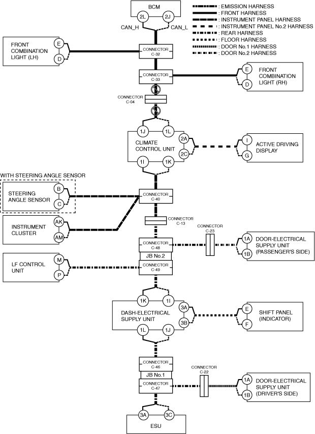
Inspection item
-
• Connector C-04• Connector C-33• Wiring harness between climate control unit terminal 1J and connector C-04• Wiring harness between climate control unit terminal 1L and connector C-04• Wiring harness between connector C-04 and connector C-33• Climate control unit
-
― Between climate control unit terminal 1I and climate control unit terminal 1J― Between climate control unit terminal 1K and climate control unit terminal 1L
-
Q
Possible cause
-
• Connector terminal disconnection, poor contact, damage, deformation, corrosion• Front combination light (RH) power supply voltage or body ground malfunction• Open circuit in wiring harness between front combination light (RH) and connector C-33• Connector C-33 malfunction• Front combination light (RH) malfunction
System wiring diagram
am3zzw00027562
|
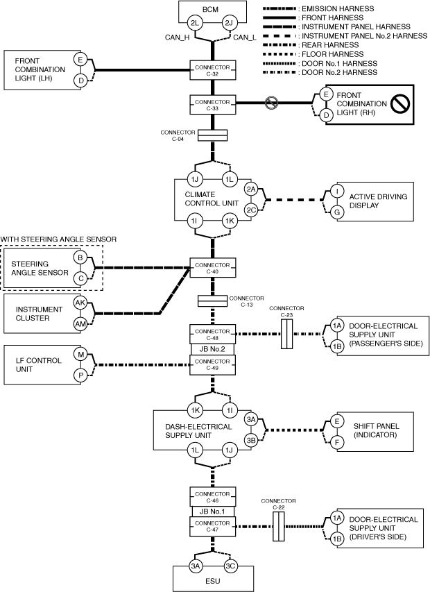
Inspection item
-
• Front combination light (RH) power supply voltage-related wiring harness and fuse• Front combination light (RH) body ground related wiring harness• Front combination light (RH) connector• Connector C-33• Wiring harness between front combination light (RH) terminal E and connector C-33• Wiring harness between front combination light (RH) terminal D and connector C-33• Front combination light (RH)
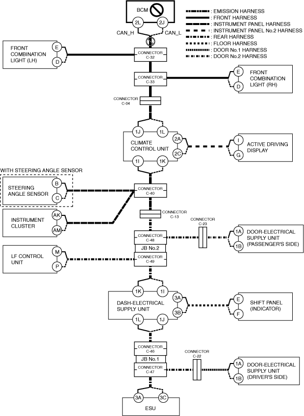
R
Possible cause
-
• Connector terminal disconnection, poor contact, damage, deformation, corrosion• Open circuit in wiring harness between connector C-33 and connector C-32• Connector C-33 malfunction• Connector C-32 malfunction
System wiring diagram
am3zzw00027563
|
Inspection item
-
• Connector C-33• Connector C-32• Wiring harness between connector C-33 and connector C-32
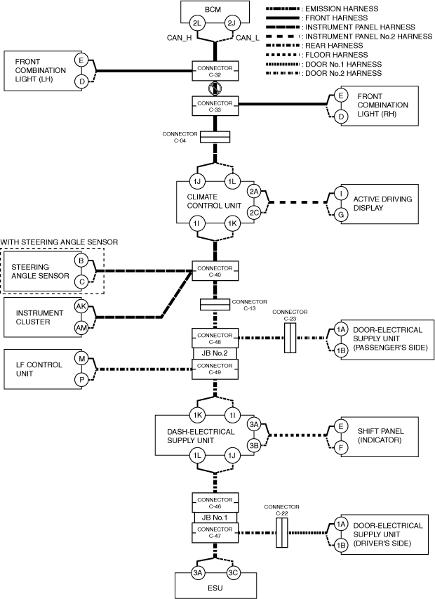
S
Possible cause
-
• Connector terminal disconnection, poor contact, damage, deformation, corrosion• Front combination light (LH) power supply voltage or body ground malfunction• Open circuit in wiring harness between front combination light (LH) and connector C-32• Connector C-32 malfunction• Front combination light (LH) malfunction
System wiring diagram
am3zzw00027564
|
Inspection item
-
• Front combination light (LH) power supply voltage-related wiring harness and fuse• Front combination light (LH) body ground related wiring harness• Front combination light (LH) connector• Connector C-32• Wiring harness between front combination light (LH) terminal E and connector C-32• Wiring harness between front combination light (LH) terminal D and connector C-32• Front combination light (LH)
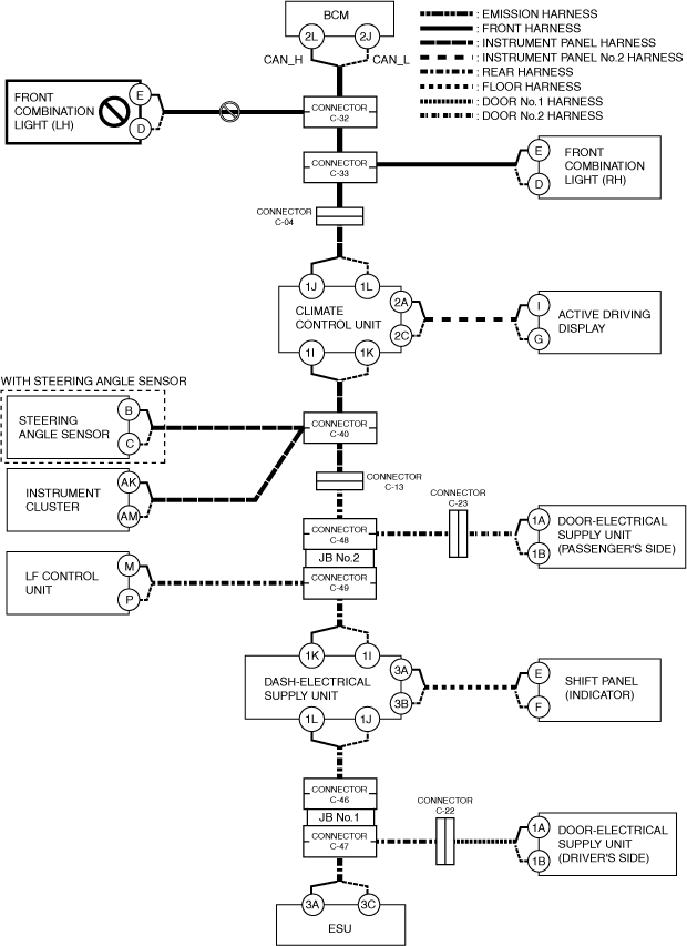
T
Possible cause
-
• Connector terminal disconnection, poor contact, damage, deformation, corrosion• Body control module (BCM) power supply voltage or body ground malfunction• Open circuit in wiring harness between body control module (BCM) and connector C-32• Connector C-32 malfunction• Body control module (BCM) malfunction
System wiring diagram
am3zzw00027565
|
Inspection item
-
• Body control module (BCM) power supply voltage-related wiring harness and fuse• Body control module (BCM) body ground related wiring harness• Body control module (BCM) connector• Connector C-32• Wiring harness between Body control module (BCM) terminal 2L and connector C-32• Wiring harness between Body control module (BCM) terminal 2J and connector C-32• Body control module (BCM)