AIR FUEL RATIO (A/F) SENSOR INSPECTION [SKYACTIV-G (WITHOUT CYLINDER DEACTIVATION (US))]
AIR FUEL RATIO (A/F) SENSOR INSPECTION [SKYACTIV-G (WITHOUT CYLINDER DEACTIVATION (US))]
SM2565880
id0140u0899600
A/F Sensor Inspection
1.Connect the M-MDS to the DLC‐2.
2.Switch the ignition ON (engine on).
3.Warm up the engine to normal operating temperature.
4.Access the following PIDs using the M-MDS. (See PID/DATA MONITOR INSPECTION.)
-
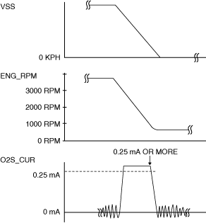
― VSS (Vehicle speed)― ENG_RPM (Engine speed)― O2S_CUR (A/F sensor output current)
5.Drive the vehicle and decelerate the engine speed by releasing the accelerator pedal fully when the engine speed is 3,000 rpm or more.
6.Verify that the A/F sensor output current (PID: O2S_CUR) is 0.25 mA or more while decelerating as shown in the figure.
am3zzw00024000
|
-
• If not as specified, replace the A/F sensor. (See AIR FUEL RATIO (A/F) SENSOR REMOVAL/INSTALLATION [SKYACTIV-G (WITHOUT CYLINDER DEACTIVATION (US))].)
A/F Sensor Heater Inspection
-
Warning
-
• A hot engine and exhaust system can cause severe burns. Turn off the engine and wait until they are cool before removing the exhaust system.
-
Caution
-
• Do not allow flammable objects such as the taping for bundling a wiring harness to come into contact with the exhaust manifold and silencer.
1.Disconnect the negative battery terminal. (See NEGATIVE BATTERY TERMINAL DISCONNECTION/CONNECTION [(US)].)
2.Disconnect the A/F sensor connector. (See AIR FUEL RATIO (A/F) SENSOR REMOVAL/INSTALLATION [SKYACTIV-G (WITHOUT CYLINDER DEACTIVATION (US))].)
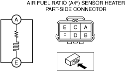
3.Measure the resistance between A/F sensor terminals A and E.
am3zzw00034789
|
-
• If not as specified, replace the A/F sensor. (See AIR FUEL RATIO (A/F) SENSOR REMOVAL/INSTALLATION [SKYACTIV-G (WITHOUT CYLINDER DEACTIVATION (US))].)
-
A/F sensor heater resistance
-
1—10 ohms [normal temperature]

