MASTER CYLINDER REMOVAL/INSTALLATION [L.H.D. (US)]
MASTER CYLINDER REMOVAL/INSTALLATION [L.H.D. (US)]
SM2565961
id041100801355
Replacement Part
|
O-ring
Quantity: 1
Location of use: Master cylinder component
|
Oil and Chemical Type
|
Brake fluid type
Type: SAE J1703 or FMVSS116 DOT-3
|
-
Caution
-
• Brake fluid will damage painted surfaces. Be careful not to spill any on painted surfaces. In addition, if there is any brake fluid on the wiring harness, the wire insulation may corrode causing a malfunction such as a short circuit. If brake fluid gets on a painted surface or wiring harness, wash and flush it off completely with water immediately.
-
Note
-
• Tighten the brake pipe flare nut using any commercially available flare nut wrench.
1.Disconnect the negative battery terminal. (See NEGATIVE BATTERY TERMINAL DISCONNECTION/CONNECTION [(US)].)
2.Remove the following parts as a single unit. (See INTAKE-AIR SYSTEM REMOVAL/INSTALLATION [SKYACTIV-G (WITH CYLINDER DEACTIVATION (US))].) (See INTAKE-AIR SYSTEM REMOVAL/INSTALLATION [SKYACTIV-G (WITH CYLINDER DEACTIVATION (US))].)
-
• Air hose• Air cleaner cover• Air cleaner element• Air cleaner case• Fresh-air duct• Resonance chamber
3.Remove the battery. (See BATTERY REMOVAL/INSTALLATION [SKYACTIV-G (WITHOUT CYLINDER DEACTIVATION (US))].) (See BATTERY REMOVAL/INSTALLATION [SKYACTIV-G (WITH CYLINDER DEACTIVATION (US))].)
4.Remove the battery tray and PCM component. (See BATTERY REMOVAL/INSTALLATION [SKYACTIV-G (WITHOUT CYLINDER DEACTIVATION (US))].) (See BATTERY REMOVAL/INSTALLATION [SKYACTIV-G (WITH CYLINDER DEACTIVATION (US))].)
5.Set the PCM wiring harness out of the way.
6.Disconnect the vacuum hose from the clip. (See VACUUM HOSE REMOVAL/INSTALLATION [SKYACTIV-G (WITHOUT CYLINDER DEACTIVATION (US))].) (See VACUUM HOSE REMOVAL/INSTALLATION [SKYACTIV-G (WITH CYLINDER DEACTIVATION (US))].)
7.Remove in the order indicated in the table.
8.Install in the reverse order of removal.
9.After installation, add brake fluid, bleed the air, and inspect for fluid leakage. (See BRAKE FLUID AIR BLEEDING [(US)].) (See CLUTCH FLUID REPLACEMENT/AIR BLEEDING [C66M-R (US)] (MTX).)
am3zzw00036458
|

|
1
|
Brake fluid level sensor connector
|
|
2
|
Clutch reserve hose (MTX)
|
|
3
|
Brake pipe
|
|
4
|
Nut
|
|
5
|
Bracket
|
|
6
|
Master cylinder component
|
|
7
|
Cap
|
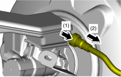
Clutch Reserve Hose Removal Note (MTX)
1.Disconnect the clutch reserve hose in the order shown in the figure.
am3zzw00025059
|
Clutch Reserve Hose Installation Note (MTX)
1.Insert the clutch reserve hose into the master cylinder.
2.Pull the clutch reserve hose to verify that it does not come off, and reinsert it completely.