PURGE SOLENOID VALVE INSPECTION [SKYACTIV-G (WITHOUT CYLINDER DEACTIVATION (US))]
PURGE SOLENOID VALVE INSPECTION [SKYACTIV-G (WITHOUT CYLINDER DEACTIVATION (US))]
SM2565770
id0116u0800900
Purge Control System Inspection
Without Using the M-MDS
1.Start the engine and idle it.
2.Remove the plug hole plate. (See PLUG HOLE PLATE REMOVAL/INSTALLATION [SKYACTIV-G (WITHOUT CYLINDER DEACTIVATION (US))].)
3.Disconnect the evaporative hose between the purge solenoid valve and the charcoal canister.
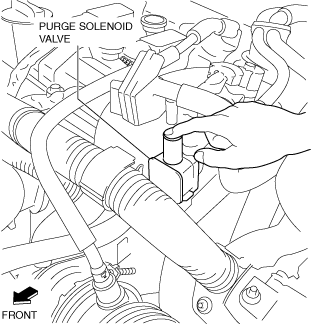
4.While idling the engine when cold, verify that vacuum is not applied by touching the purge solenoid valve with your finger as shown in the figure.
am3zzw00025128
|
-
• If vacuum is applied, inspect the following and repair or replace the malfunctioning location.
-
― PCM output signal circuit (wiring harness, connector)
-
• Evaporative purge control signal (short to ground in wiring harness between purge solenoid valve terminal A and PCM terminal 1AW)
― Purge solenoid valve (See Airflow Inspection.) -
-
5.Load the vehicle on the chassis dynamometer and drive it while maintaining the engine speed at approx. 2,000 rpm.
-
Warning
-
• When using a chassis dynamometer, be careful not to get parts such as tires or rollers caught in the rotating parts.
6. Verify that vacuum is applied after approx. 30 s.
-
• If vacuum cannot be verified, inspect the following.
-
― PCM input signal circuit (sensor, switch, wiring harness)
-
• Intake air temperature No.1 signal (IAT sensor No.1)• Evaporative purge control signal (open circuit in wiring harness between purge solenoid valve terminal A and PCM terminal 1AW)• Throttle opening angle signal (throttle position sensor)• Under load/under no-load determination signal (transaxle range sensor)
― Purge solenoid valve― Purge solenoid valve power supply circuit (open or short circuit in wiring harness between purge solenoid valve terminal B and main relay terminal) -
-
Using The M-MDS
1.Connect the M-MDS to the DLC-2.
2.Start the engine and idle it.
3.Remove the plug hole plate. (See PLUG HOLE PLATE REMOVAL/INSTALLATION [SKYACTIV-G (WITHOUT CYLINDER DEACTIVATION (US))].)
4.Disconnect the evaporative hose between the purge solenoid valve and the charcoal canister.
5.While idling the engine when cold, verify that vacuum is not applied by touching the purge solenoid valve with your finger as shown in the figure.
am3zzw00025128
|
-
• If vacuum is applied, inspect the following and repair or replace the malfunctioning location.
-
― PID: PRG_DUTY
-
-
• Evaporative purge control signal (short to ground in wiring harness between purge solenoid valve terminal A and PCM terminal 1AW)
-
― PCM output signal circuit (wiring harness, connector)― Purge solenoid valve (See Airflow Inspection.)
-
6.Connect the evaporative hose.
7.When the 0% duty value of the purge solenoid valve is operated at a 100% duty value using the simulation function [PRG_DUTY], verify that the PID [SHRT_FUEL_TRIM11] value fluctuates.(See SIMULATION INSPECTION.)
-
• If the PID [SHRT_FUEL_TRIM11] value does not change, inspect the following.
-
1. Switch the ignition OFF.2. Switch the ignition ON (engine off).3. When the 0% duty value of the purge solenoid valve is operated at a 50% duty value using the simulation function [PRG_DUTY], verify the operation sound of the purge solenoid valve. (See SIMULATION INSPECTION.)
-
-
• If the operation sound can be verified, inspect the following.
-
― Evaporative hose disconnection or damage (between intake manifold and purge solenoid valve, and purge solenoid valve and charcoal canister)
-
-
• If the operation sound cannot be verified, inspect the following.
-
― Purge solenoid valve (See Airflow Inspection.)― Open circuit in wiring harnesses and connectors (between main relay terminal and purge solenoid valve terminal B, purge solenoid valve terminal A and PCM terminal 1AW)
-
-
Warning
-
• When the M-MDS is used to observe monitor system status while driving, be sure to have another technician with you, or record the data in the M-MDS using the PID/DATA MONITOR AND RECORD capturing function and inspect later.• While performing this step, always operate the vehicle in a safe and lawful manner.
8.Drive the vehicle at an engine speed of approx. 2,000 rpm for 30 s or more.
9.Verify that the PID [PRG_DUTY] value fluctuates between 0% and 100%.
-
• If the PID [PRG_DUTY] value fluctuation cannot be verified, inspect the following and repair or replace the malfunctioning location.
-
― PCM input signal circuit (sensor, switch, wiring harness)― Intake air temperature No.1 signal (IAT sensor No. 1)― Throttle opening angle signal (throttle position sensor)― Under load/under no-load determination signal (transaxle range sensor)
-
Airflow Inspection
1.Disconnect the negative battery terminal. (See NEGATIVE BATTERY TERMINAL DISCONNECTION/CONNECTION [(US)].)
2.Remove the purge solenoid valve. (See PURGE SOLENOID VALVE REMOVAL/INSTALLATION [SKYACTIV-G (WITHOUT CYLINDER DEACTIVATION (US))].)
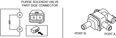
3.Inspect airflow between the ports under the following conditions.
am3zzw00034773
|
|
Measured condition |
Continuity between ports A—B |
|---|---|
|
When voltage is not applied between terminals A and B
|
No airflow
|
|
When voltage is applied between terminals A and B
|
Airflow detected
|
-
• If not as specified, replace the purge solenoid valve. (See PURGE SOLENOID VALVE REMOVAL/INSTALLATION [SKYACTIV-G (WITHOUT CYLINDER DEACTIVATION (US))].)