TIMING CHAIN REMOVAL/INSTALLATION [SKYACTIV-G (WITHOUT CYLINDER DEACTIVATION (US))]
TIMING CHAIN REMOVAL/INSTALLATION [SKYACTIV-G (WITHOUT CYLINDER DEACTIVATION (US))]
SM2565607
id0110u0801000
Special Service Tool (SST)
|
1. : Mazda SST number
2. : Global SST number
|
|||||
|
1: 49 C017 5A0
2: –
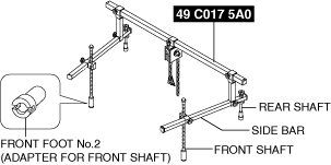
Engine support set
|
 |
1: 49 UN30 3050
2: 303–050
Engine lifting bracket
|
 |
1: 49 L017 5A0
2: –
Support hanger
|
 |
Replacement Part
|
Washer
Quantity: 1
Location of use: Engine front cover
|
O-ring
Quantity: 1
Location of use: Electric variable valve timing motor/driver
|
Cylinder head cover gasket
Quantity: 1
Location of use: Cylinder head cover
|
|
Front oil seal
Quantity: 1
Location of use: Engine front cover
|
—
|
—
|
-
Warning
-
• A hot engine can cause severe burns. Turn off the engine and wait until it is cool before servicing.
-
Caution
-
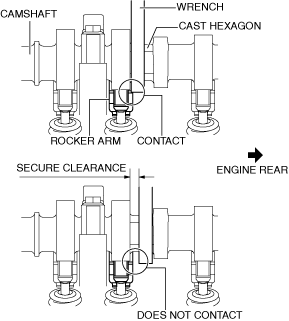
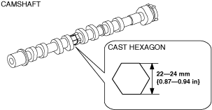
• If the camshaft is rotated with the timing chain removed and the piston at the top dead center position, the valve may contact the piston and the engine could be damaged. When rotating the camshaft with the timing chain removed, rotate it after lowering the piston from the top dead center position.• When rotating the camshaft using a wrench on the cast hexagon, the wrench may contact the rocker arm and damage the rocker arm. To prevent damage to the rocker arm when holding the camshaft on the cast hexagon, use a wrench on the rear side of the engine as shown in the figure to secure a clearance between the cam.
 ac5wzw00003212
-
Note
-
• Width at the cast hexagon of the camshaft is 22—24 mm {0.87—0.94 in}.am6xuw00006584
1.Disconnect the negative battery terminal. (See NEGATIVE BATTERY TERMINAL DISCONNECTION/CONNECTION [(US)].)
2.Remove the plug hole plate. (See PLUG HOLE PLATE REMOVAL/INSTALLATION [SKYACTIV-G (WITH CYLINDER DEACTIVATION (US))].)
3.Remove the ignition coil/ion sensors. (See IGNITION COIL/ION SENSOR REMOVAL/INSTALLATION [SKYACTIV-G (WITHOUT CYLINDER DEACTIVATION (US))].)
4.Remove the front under cover No.2. (See FRONT UNDER COVER No.2 REMOVAL/INSTALLATION.)
5.Remove the splash shield. (See SPLASH SHIELD REMOVAL/INSTALLATION.)
6.Remove the drive belt. (See DRIVE BELT REMOVAL/INSTALLATION [SKYACTIV-G (WITHOUT CYLINDER DEACTIVATION (US))].)
7.Drain the engine oil. (See ENGINE OIL REPLACEMENT [SKYACTIV-G (WITHOUT CYLINDER DEACTIVATION (US))].)
8.Remove the oil pan. (See OIL PAN REMOVAL/INSTALLATION [SKYACTIV-G (WITHOUT CYLINDER DEACTIVATION (US))].)
9.Remove in the order indicated in the table.
10.Install in the reverse order of removal.
11.Refill with the specified type and amount of the engine oil. (See ENGINE OIL REPLACEMENT [SKYACTIV-G (WITHOUT CYLINDER DEACTIVATION (US))].)
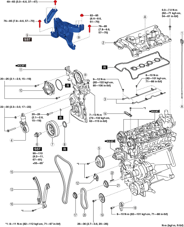
SKYACTIV-G 2.0
am3zzw00024913
|
|
1
|
Dipstick
|
|
2
|
Cylinder head cover
|
|
3
|
Oil shower pipe
|
|
4
|
Drive belt auto tensioner
|
|
5
|
Water pump pulley
|
|
6
|
Crankshaft pulley lock bolt
|
|
7
|
Crankshaft pulley
|
|
8
|
Front oil seal
|
|
9
|
No.3 engine mount
|
|
10
|
Electric variable valve timing motor/driver
|
|
11
|
Engine front cover
|
|
12
|
Chain tensioner
(See Timing Chain Removal Note.)
|
|
13
|
Tensioner arm
(See Timing Chain Removal Note.)
|
|
14
|
Chain guide (No.1)
(See Timing Chain Removal Note.)
|
|
15
|
Timing chain
(See Timing Chain Removal Note.)
|
|
16
|
Chain guide (No.2)
|
|
17
|
Crankshaft sprocket
|
|
18
|
Oil pump chain tensioner
|
|
19
|
Oil pump driven sprocket
|
|
20
|
Oil pump chain
|
|
21
|
Oil pump drive sprocket
|
|
22
|
Key
|
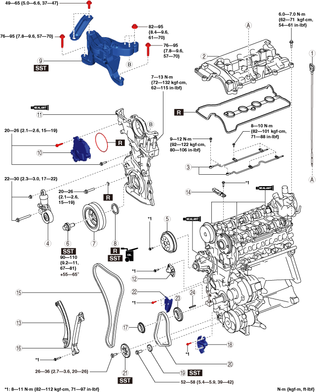
SKYACTIV-G 2.5
am3zzw00028586
|
|
1
|
Dipstick
|
|
2
|
Cylinder head cover
|
|
3
|
Oil shower pipe
|
|
4
|
Drive belt auto tensioner
|
|
5
|
Water pump pulley
|
|
6
|
Crankshaft pulley lock bolt
|
|
7
|
Crankshaft pulley
|
|
8
|
Front oil seal
|
|
9
|
No.3 engine mount
|
|
10
|
Electric variable valve timing motor/driver
|
|
11
|
Engine front cover
|
|
12
|
Chain tensioner
(See Timing Chain Removal Note.)
|
|
13
|
Tensioner arm
(See Timing Chain Removal Note.)
|
|
14
|
Chain guide (No.1)
(See Timing Chain Removal Note.)
|
|
15
|
Timing chain
(See Timing Chain Removal Note.)
|
|
16
|
Chain guide (No.2)
|
|
17
|
Crankshaft sprocket
|
|
18
|
Oil pump chain tensioner
|
|
19
|
Balancer shaft sprocket
|
|
20
|
Oil pump chain
|
|
21
|
Oil pump driven sprocket
|
|
22
|
Oil pump chain guide
|
|
23
|
Oil pump drive sprocket
|
|
24
|
Key
|
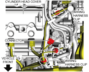
Cylinder Head Cover Removal Note
1.Disconnect the OCV connector.
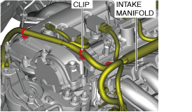
2.Remove the wiring harness clips secured to the cylinder head cover.
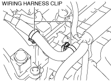
3.Remove the wiring harness clip secured to the intake manifold as shown in the figure, and set the wiring harness aside.
am3zzw00024914
|
4.Disconnect the ventilation hose.
5.Disconnect the brake vacuum hose from the intake manifold and set it aside.
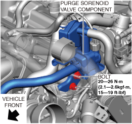
6.Set aside the purge solenoid valve component using the following procedure.
- (1)Remove the wiring harness clips and connectors shown in the figure.
-
ac5uuw00009332
- (2)Remove the bolts shown in the figure.
-
am3zzw00031754
- (3)Set the following parts aside as a single unit with the evaporative hose connected.
-
-
• Purge solenoid valve• Catch tank• Bracket
-
7.Remove the cylinder head cover.
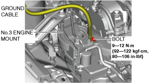
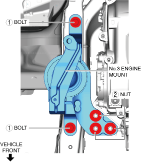
No.3 Engine Mount Removal Note
1.Set the cooler hose (LO) aside. (See REFRIGERANT LINE REMOVAL/INSTALLATION [SKYACTIV-G 2.0, SKYACTIV-G 2.5].)
2.Remove the clips shown in the figure and set the ground cable aside.
am3zzw00024915
|
-
Caution
-
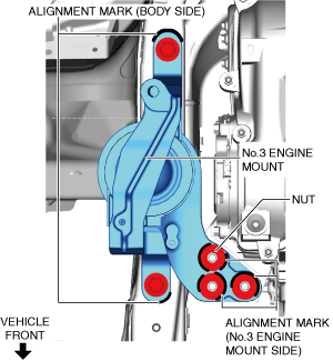
• Slots have been adopted for the No.3 engine mount installation holes. If the No.3 engine mount is deviated from the original position when installing the No.3 engine mount, engine noise or vibration could increase. Before removing the No.3 engine mount, place alignment marks on the No.3 engine mount and body so that they can be assembled to the same positions as before removal.
3.Place alignment marks on the locations shown in the figure so that they can be assembled to the same positions as before removal.
am3zzw00024917
|
-
Note
-
• Paint so that the No.3 engine mount is framed on the body side and the outline of the nut is framed on the No.3 engine mount side.
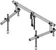
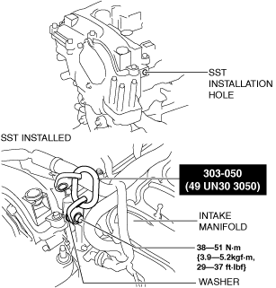
4.Install the SST using the following procedures.
ac5uuw00006422
|
-
Caution
-
• Refer to the SST instruction manual for the basic handing procedure.
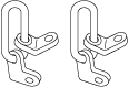
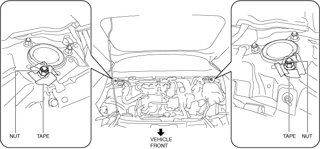
- (1)Install one front foot No.2 to each of the left and right front shafts of the SST.
- (2)Protect the positions shown in the area using tape.
-
am3zzw00022349
- (3)Remove the coolant reserve tank. (See COOLANT RESERVE TANK REMOVAL/INSTALLATION [SKYACTIV-G (WITH CYLINDER DEACTIVATION (US))].)
- (4)To enable installation of the SST, disconnect the wiring harness clips shown in the figure and set the wiring harness aside.
-
am3zzw00022350
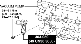
- (5)Install the SST using a bolt with part number 99794 1025 or an M10—1.25, length 25 mm {0.98 in} bolt, and a washer as shown in the figure.
-
Engine front side
am3zzw00031755Engine rear side
am3zzw00031756
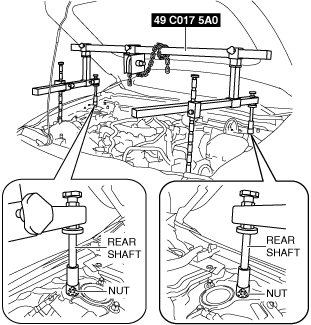
- (6)As shown in the figure, set the rear shafts of the SST to the left and right front shock absorber nuts.
-
am3zzw00022352
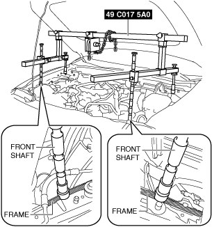
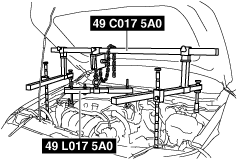
- (7)Set the front shafts of the SST (49 C017 5A0) as shown in the figure.
-
am3zzw00022353
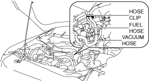
- (8)To prevent interference of the SST with the hose when assembling the SST (49 L017 5A0), disconnect the hose clip from the bracket shown in the figure and set the fuel hose and vacuum hose aside.
-
am3zzw00022354
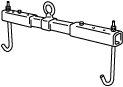
- (9)Install the SST (49 L017 5A0) to the SST (49 C017 5A0) as shown in the figure.
-
am3zzw00022355
- (10)Install the SST (49 L017 5A0) to the SST (49 UN30 3050) with the hook of the SST (49 L017 5A0) facing outward.
-
am3zzw00022356
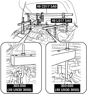
- (11)Adjust the height of the left and right side bars so that they are leveled, then tighten each part of the SST.
- (12)Apply tension to the chain to support the engine and verify that the engine is securely hung.
5.Remove the No.3 engine mount.
Engine Front Cover Removal Note
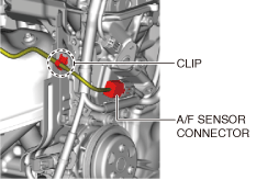
1.Disconnect the A/F sensor connector and clip shown in the figure.
am3zzw00031757
|
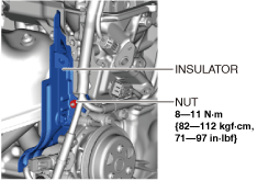
2.Remove the insulator shown in the figure.
am3zzw00031758
|
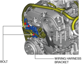
3.Set the wiring harness bracket shown in the figure aside.
am3zzw00024918
|
4.Remove the engine front cover installation bolts.
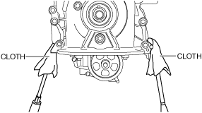
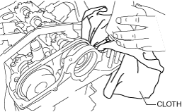
5.Using a screwdriver wrapped in a cloth, peel the silicone sealant away a little at a time, and remove the engine front cover.
-
Caution
-
• Do not apply excessive force to the screwdriver. Otherwise, the engine front cover could be damaged.• Be careful not to scratch or damage the seal surface. Otherwise, it could cause oil leakage.am3zzw00024919am3zzw00024920
Timing Chain Removal Note
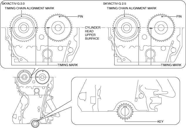
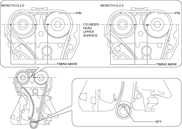
1.Rotate the crankshaft clockwise to align the timing marks and the key position as shown in the figure, and set cylinder No.1 at top dead center (TDC).
am3zzw00024921
|
-
Note
-
• The timing mark of SKYACTIV-G 2.5 is not parallel with the upper surface of the cylinder head.
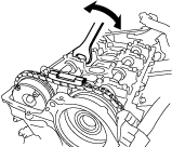
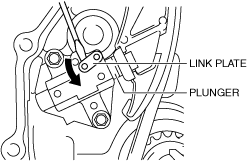
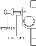
2.While moving the exhaust camshaft back and forth in the direction of the arrow using a wrench on the cast hexagon, press down the link plate of the timing chain tensioner using a precision screwdriver and release the plunger lock.
ac5wzw00003229
|
am3zzw00024922
|
-
Note
-
• When moving the exhaust camshaft back and forth, the timing chain pushes the plunger in the chain tensioner making it easier to operate the link plate.
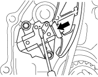
3.Push back the plunger slowly in the direction shown in the figure with the link plate still pushed down.
ac5wzw00003231
|
4.Remove the screwdriver from the link plate with the plunger still pushed down.
5.Release the force slightly from the plunger, and move it back and forth 2—3 mm {0.08—0.11 in}.
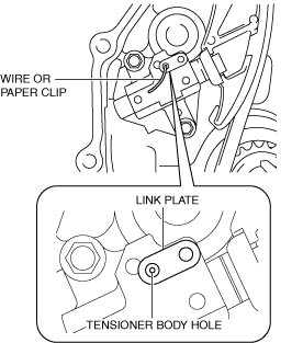
6.Insert a wire with an approx. diameter of 1.5 mm {0.059 in} or a paper clip where the link plate hole and the tensioner body hole overlap to secure the link plate and lock the plunger.
am3zzw00024923
|
7.Remove the chain tensioner, tensioner arm, and the chain guide (No.1).
8.Remove the timing chain.
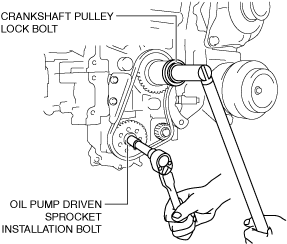
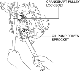
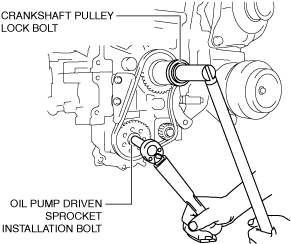
Oil Pump Driven Sprocket Removal Note (SKYACTIV-G 2.0)
1.Temporarily assemble the crankshaft pulley lock bolt, and lock the oil pump against rotation as shown in the figure.
am3zzw00024924
|
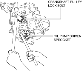
2.Remove the oil pump driven sprocket.
3.Remove the temporarily assembled crankshaft pulley lock bolt.
Oil Pump Chain Removal Note (SKYACTIV-G 2.5)
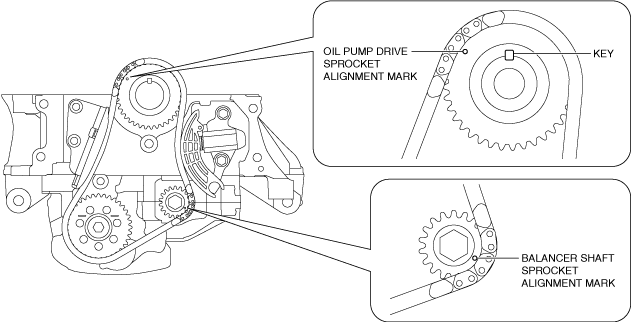
1.Verify that the balancer shaft sprocket alignment mark and key are aligned to the positions shown in the figure.
ac5wzw00010909
|
2.Slightly loosen the balancer shaft sprocket installation bolt using the following procedure:
-
Note
-
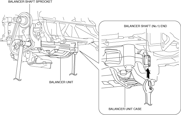
• At this stage, only loosen the installation bolt, do not remove it. Remove the bolt after removing the oil pump chain tensioner.• The balancer unit is constructed such that the end of the balancer shaft (No.1) protrudes from the balancer unit case. The balancer shaft (No.1) can be locked against rotation by holding the end using a wrench.ac5wzw00010910
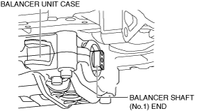
- (1)Lock the balancer shaft (No.1) against rotation as shown in the figure.
-
-
Caution
-
• To prevent damage to the balancer unit, protect the end of the balancer shaft (No.1) with a clean cloth.
ac5wzw00010911 -
- (2)Slightly loosen the balancer shaft sprocket installation bolt.
3.Slightly loosen the oil pump driven sprocket installation bolt using the following procedure:
-
Note
-
• At this stage, only loosen the installation bolt, do not remove it. Remove the bolt after removing the oil pump chain tensioner.
- (1)Temporarily assemble the crankshaft pulley lock bolt, and lock the oil pump against rotation as shown in the figure.
-
am3uuw00015892
- (2)Slightly loosen the oil pump driven sprocket installation bolt.
- (3)Remove the temporarily assembled crankshaft pulley lock bolt.
4.Set a cloth wrapped flathead screwdriver in the gap between the oil pump drive sprocket and the oil pump chain as shown in the figure.
ac5wzw00011256
|
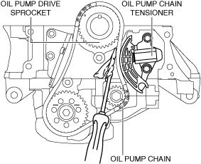
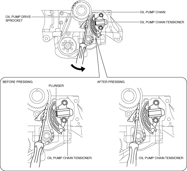
5.Move the screwdriver in the direction of the arrow and press the oil pump chain, and then press on the plunger of the oil pump chain tensioner.
ac5wzw00010913
|
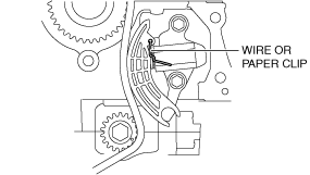
6.Insert a wire with an approx. diameter of 1.4 mm {0.055 in} or a paper clip into the body hole of the oil pump chain tensioner with the plunger pressed.
ac5wzw00010914
|
-
Note
-
• The wire or paper clip secures the plunger, and the tension can be released.
7.Remove the oil pump chain tensioner.
8.Remove the oil pump chain and balancer shaft sprocket as a single unit.
9.Remove the oil pump driven sprocket.
Oil Pump Driven Sprocket Installation Note (SKYACTIV-G 2.0)
1.Temporarily assemble the crankshaft pulley lock bolt, and lock the oil pump against rotation as shown in the figure.
am3zzw00024925
|
2.Install the oil pump driven sprocket.
3.Remove the temporarily assembled crankshaft pulley lock bolt.
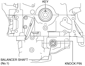
Oil Pump Chain Installation Note (SKYACTIV-G 2.5)
1.Verify that the key and knock pin are aligned to the positions shown in the figure.
ac5wzw00010915
|
2.Temporarily assemble the oil pump driven sprocket.
3.Temporarily tighten the oil pump driven sprocket installation bolt.
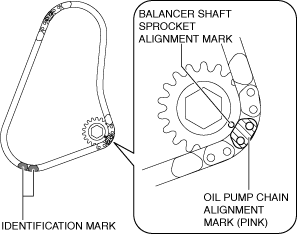
4.Align the oil pump chain alignment mark with the balancer shaft sprocket alignment mark.
ac5wzw00010916
|
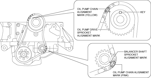
5.Install the oil pump chain and balancer shaft sprocket as a single unit while aligning the alignment marks on each sprocket and oil pump chain as shown in the figure.
ac5wzw00010917
|
6.Temporarily tighten the balancer shaft sprocket installation bolt.
7.Install the oil pump chain tensioner.
-
Caution
-
• At this stage, do not remove the wire or paper clip installed to the oil pump chain tensioner.
8.Tighten the oil pump driven sprocket installation bolt using the following procedure:
- (1)Temporarily assemble the crankshaft pulley lock bolt, and lock the oil pump against rotation as shown in the figure.
-
ac5uuw00003191
- (2)Tighten the oil pump driven sprocket installation bolt.
- (3)Remove the temporarily assembled crankshaft pulley lock bolt.
9.Tighten the balancer shaft sprocket installation bolt using the following procedure:
-
Note
-
• The balancer unit is constructed such that the end of the balancer shaft (No.1) protrudes from the balancer unit case. The balancer shaft (No.1) can be locked against rotation by holding the end using a wrench.ac5wzw00010910
- (1)Lock the balancer shaft (No.1) against rotation as shown in the figure.
-
-
Caution
-
• To prevent damage to the balancer unit, protect the end of the balancer shaft (No.1) with a clean cloth.
ac5wzw00010918 -
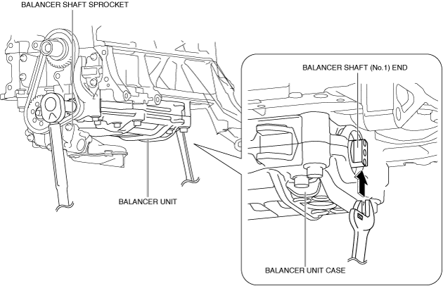
- (2)Tighten the balancer shaft sprocket installation bolt.
10.Remove the wire or paper clip installed to the oil pump chain tensioner and apply tension to the oil pump chain.
-
• If a new oil pump chain tensioner is used, remove the installed stopper.
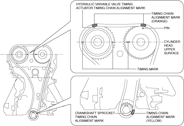
Timing Chain Installation Note
1.Verify that the timing marks and the key are aligned to the position shown in the figure.
am3zzw00024921
|
-
Note
-
• The timing mark of SKYACTIV-G 2.5 is not parallel with the upper surface of the cylinder head.
2.Install the timing chain while aligning the marks on each sprocket and the timing chain as shown in the figure.
SKYACTIV-G 2.0
am3zzw00024926
|
SKYACTIV-G 2.5
am6xuw00010502
|
3.Install the chain guide (No.1).
4.Install the tensioner arm.
5.Install the chain tensioner.
6.After installing the chain tensioner, remove the installed wire or paper clip, and then apply tension to the timing chain.
-
• If a new chain tensioner is used, remove the installed stopper.am3zzw00024927
7.Verify that there is no looseness in the timing chain, and re-verify that each sprocket is in the specified location.
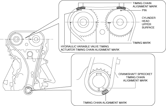
8.Rotate the crankshaft clockwise two turns and inspect the valve timing.
am3zzw00024928
|
-
Note
-
• The timing mark of SKYACTIV-G 2.5 is not parallel with the upper surface of the cylinder head.
Engine Front Cover Installation Note
-
Note
-
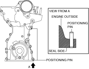
• For a new engine front cover, the positioning pins in the two locations shown in the figure project to the outside of the engine.am3zzw00024929
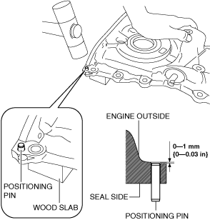
1.If the engine front cover is newly replaced, tap the positioning pins in the two locations to the seal surface side.
am3zzw00024930
|
-
Caution
-
• If a bolt with silicone sealant adhering to it is used, it could result in cracks in the cylinder head and cylinder block.am3zzw00024931
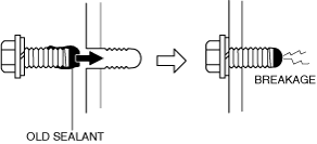
2.When reusing the engine front cover installation bolts, remove sealant adhering to the bolts.
-
Caution
-
• If oil, dirt and silicone sealant remains on the silicone sealant application area, the silicone sealant will not seal which will cause oil leakage.
3.Completely clean and remove oil, dirt, silicone sealant or other foreign matter that may be adhering to the engine front cover, cylinder head, and cylinder block.
-
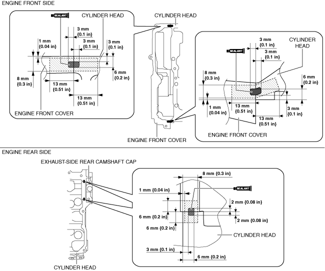
Caution
-
• Apply the silicone sealant in a single, unbroken line.• To prevent silicone sealant from hardening, adhere the engine front cover and the cylinder block firmly within 10 min. after applying silicone sealant. After adhering them, tighten the installation bolts immediately.
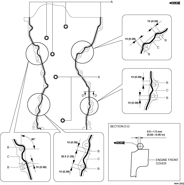
4.Apply silicone sealant (TB1217D or equivalent) to the engine front cover as shown in the figure.
SKYACTIV-G 2.0
am3zzw00024932
|
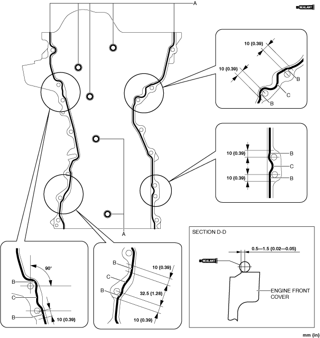
SKYACTIV-G 2.5
am3zzw00024933
|
-
Bead thickness
-
A: 2—6 mm {0.1—0.2 in}B: 4—6 mm {0.16—0.23 in}C: 4—8 mm {0.2—0.3 in}
-
Caution
-
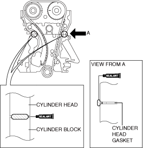
• Apply the silicone sealant so that it goes into the cylinder head gasket.
5.Apply silicone sealant (TB1217D or equivalent) to the areas shown in the figure.
am3zzw00024934
|
6.Install the engine front cover to the engine.
-
Note
-
• Temporarily install an appropriate bolt to the drive belt auto tensioner installation bolt hole to prevent:
-
― A silicone sealant adhesion malfunction in the drive belt auto tensioner installation bolt hole.― A bolt mis-installation due to silicone sealant hardening.
am3zzw00024935 -
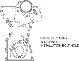
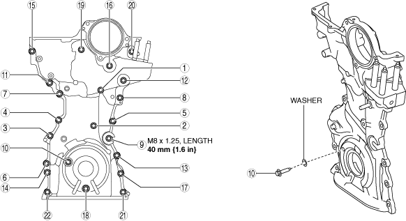
7.Prepare an appropriate M8 x 1.25 bolt (length 40 mm {1.6 in}).
-
Caution
-
• For the number 10 bolt of the tightening order, install the bolts with new washer.
8.Tighten the engine front cover installation bolts in the order shown in the figure.
am3zzw00024936
|
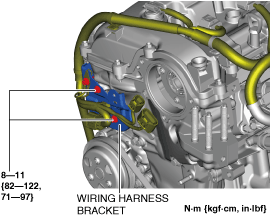
9.Install the wiring harness bracket shown in the figure.
am3zzw00024937
|
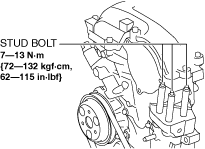
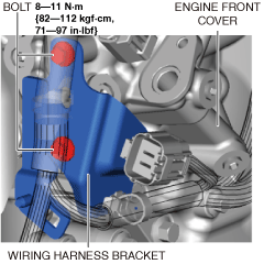
10.Tighten the engine front cover stud bolts.
am3zzw00031759
|
11.Install the wiring harness bracket shown in the figure.
am3zzw00031760
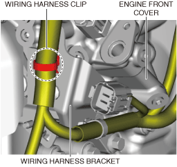
|
12.Install the wiring harness clip shown in the figure.
am3zzw00031761
|
13.Install the insulator shown in the figure.
am3zzw00031758
|
14.Connect the A/F sensor connector and clip shown in the figure.
am3zzw00031757
|
No.3 Engine Mount Installation Note
-
Caution
-
• If the No.3 engine mount is deviated from the original position when installing the No.3 engine mount, engine noise or vibration could increase. When installing the No.3 engine mount, align the alignment mark placed during removal and install it to the original position.
-
Note
-
• When replacing the No.3 engine mount, place a mark at the same position as the one placed before removal.
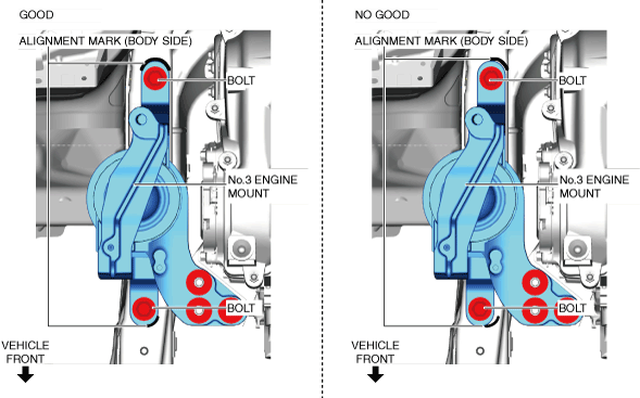
1.Temporarily tighten the No.3 engine mount installation bolts and nuts using the following procedure:
- (1)Align the alignment marks on the body side and No.3 engine mount, and temporarily tighten the bolts shown in the figure.
-
am3zzw00024939
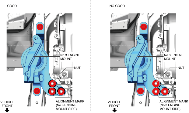
- (2)Temporarily tighten the nuts shown in the figure while aligning the alignment marks of the No.3 engine mount and nuts.
-
-
• If the alignment marks are not aligned, align the alignment marks while slightly moving the engine and temporarily tighten the nuts.
am3zzw00024940 -
2.Tighten the No.3 engine mount installation bolts and nuts in the order shown in the figure.
am3zzw00024941
|
3.Remove the SST.
4.Install the clip of ground cable to the No.3 engine mount.
am3zzw00024915
|
5.Install the cooler hose (LO). (See REFRIGERANT LINE REMOVAL/INSTALLATION [SKYACTIV-G 2.0, SKYACTIV-G 2.5].)
Drive Belt Auto Tensioner Installation Note
1.Remove the temporarily assembled bolt at the location shown in the figure.
am3zzw00024935
|
2.Install the drive belt auto tensioner. (See DRIVE BELT AUTO TENSIONER REMOVAL/INSTALLATION [SKYACTIV-G (WITHOUT CYLINDER DEACTIVATION (US))].)
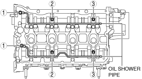
Oil Shower Pipe Installation Note
1.Temporarily tighten the oil shower pipe installation bolts.
2.Install the oil shower pipe in the order shown in the figure.
am3zzw00024942
|
Cylinder Head Cover Installation Note
-
Caution
-
• To assure the sealing performance of the cylinder head cover, be careful of the following:
-
― Verify that the cylinder head cover gasket is inserted into the cylinder head cover groove and install the cylinder head cover.― Completely clean and remove any oil, dirt, silicone sealant or other foreign matter from the seal surface.
• To prevent silicone sealant from hardening, adhere the cylinder head cover and the cylinder head firmly within 10 min. after applying silicone sealant. After adhering them, tighten the installation bolts immediately. -
1.Insert a new cylinder head cover gasket into the cylinder head cover groove.
2.Apply silicone sealant (TB1217D or equivalent) to the areas shown in the figure.
ac5wzw00010927
|
3.Install the cylinder head cover.
4.Temporarily tighten the cylinder head cover bolts.
5.Tighten the cylinder cover bolts in the order shown in the figure.
am3zzw00024944
|
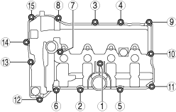
6.Measure the tightening torque again and verify that it is 6.0 N·m {61 kgf·cm, 53 in·lbf} or more.
7.Install the purge solenoid valve component using the following procedure.
- (1)Tighten the bolts shown in the figure.
-
am3zzw00031754
- (2)Install the wiring harness clips and connectors shown in the figure.
-
ac5uuw00009332
8.Connect the vacuum hose.
9.Connect the ventilation hose.
10.Return the wiring harness which was set away from the cylinder head cover and the intake manifold to its original position.
11.Connect the OCV connector.