CYLINDER HEAD GASKET REPLACEMENT [SKYACTIV-G (WITHOUT CYLINDER DEACTIVATION (US))]
CYLINDER HEAD GASKET REPLACEMENT [SKYACTIV-G (WITHOUT CYLINDER DEACTIVATION (US))]
SM2565604
id0110u0800700
Replacement Part
|
O-ring
Quantity: 2
Location of use: Water inlet pipe
|
Gasket
Quantity: 1
Location of use: Flange
|
Cylinder head gasket
Quantity: 1
Location of use: Cylinder head
|
|
Bolt [SKYACTIV-G 2.0]
Quantity: 1
Location of use: Water inlet pipe
|
—
|
—
|
Oil and Chemical Type
|
Engine oil
Type: Recommended oil
|
Gear oil
Type: SAE 90 gear oil or equivalent
|
Sealant
Type: LOCTITE 962T or equivalent
|
|
Silicone sealant
Type: TB1217D or equivalent
|
Coolant
Type: Recommended coolant
|
—
|
-
Warning
-
• A hot engine can cause severe burns. Turn off the engine and wait until it is cool before servicing.• Fuel vapor is hazardous. It can very easily ignite, causing serious injury and damage. Always keep sparks and flames away from fuel.• Highly pressurized fuel may spray out if the fuel line is cut. Due to the following dangers occurring with a fuel spray, always complete the “Fuel Line Safety Procedure” to prevent the fuel from spraying.
-
― Fuel may cause irritation if it comes in contact with skin and eyes.― If fuel ignites and causes a fire, it may lead to serious injury or death, and damage to property and facilities.
-
-
Caution
-
• If the camshaft is rotated with the timing chain removed and the piston at the top dead center position, the valve may contact the piston and the engine could be damaged. When rotating the camshaft with the timing chain removed, rotate it after lowering the piston from the top dead center position.
1.Disconnect the negative battery terminal. (See NEGATIVE BATTERY TERMINAL DISCONNECTION/CONNECTION [(US)].)
2.Remove the plug hole plate. (See PLUG HOLE PLATE REMOVAL/INSTALLATION [SKYACTIV-G (WITH CYLINDER DEACTIVATION (US))].)
3.Remove the ignition coil/ion sensors. (See IGNITION COIL/ION SENSOR REMOVAL/INSTALLATION [SKYACTIV-G (WITHOUT CYLINDER DEACTIVATION (US))].)
4.Remove the front under cover No.2. (See FRONT UNDER COVER No.2 REMOVAL/INSTALLATION.)
5.Remove the front splash shield (RH). (See SPLASH SHIELD REMOVAL/INSTALLATION.)
6.Remove the drive belt. (See DRIVE BELT REMOVAL/INSTALLATION [SKYACTIV-G (WITHOUT CYLINDER DEACTIVATION (US))].)
7.Drain the engine oil. (See ENGINE OIL REPLACEMENT [SKYACTIV-G (WITHOUT CYLINDER DEACTIVATION (US))].)
8.Drain the engine coolant. (See ENGINE COOLANT REPLACEMENT [SKYACTIV-G (WITH CYLINDER DEACTIVATION (US))].)
9.Remove the intake manifold. (See INTAKE-AIR SYSTEM REMOVAL/INSTALLATION [SKYACTIV-G (WITH CYLINDER DEACTIVATION (US))].)
10.Set aside the exhaust manifold to the vehicle rear. (See EXHAUST SYSTEM REMOVAL/INSTALLATION [SKYACTIV-G (WITH CYLINDER DEACTIVATION (US))].)
11.Remove the vacuum pump. (See VACUUM PUMP REMOVAL/INSTALLATION [SKYACTIV-G (WITHOUT CYLINDER DEACTIVATION (US))].)
12.Remove the high pressure fuel pump and rear housing. (See HIGH PRESSURE FUEL PUMP REMOVAL/INSTALLATION [SKYACTIV-G (WITHOUT CYLINDER DEACTIVATION (US))].)
13.Disconnect the heater hose from the coolant control valve and flange.
14.Disconnect the water hose No.1 from the flange. (ATX) (See OIL COOLER REMOVAL/INSTALLATION [ET6A-EL (SKYACTIV-G 2.0, SKYACTIV-G 2.5) (US)].)
15.Disconnect the water hose No.2 from the coolant control valve. (ATX) (See OIL COOLER REMOVAL/INSTALLATION [ET6A-EL (SKYACTIV-G 2.0, SKYACTIV-G 2.5) (US)].)
16.Removal the coolant control valve. (See COOLANT CONTROL VALVE REMOVAL/INSTALLATION [SKYACTIV-G (WITH CYLINDER DEACTIVATION (US))].)
17.Remove the oil pan. (See OIL PAN REMOVAL/INSTALLATION [SKYACTIV-G (WITHOUT CYLINDER DEACTIVATION (US))].)
18.Remove the timing chain and chain guide. (See TIMING CHAIN REMOVAL/INSTALLATION [SKYACTIV-G (WITHOUT CYLINDER DEACTIVATION (US))].)
19.Remove the OCV. (See OIL CONTROL VALVE (OCV) REMOVAL/INSTALLATION [SKYACTIV-G (WITHOUT CYLINDER DEACTIVATION (US))].)
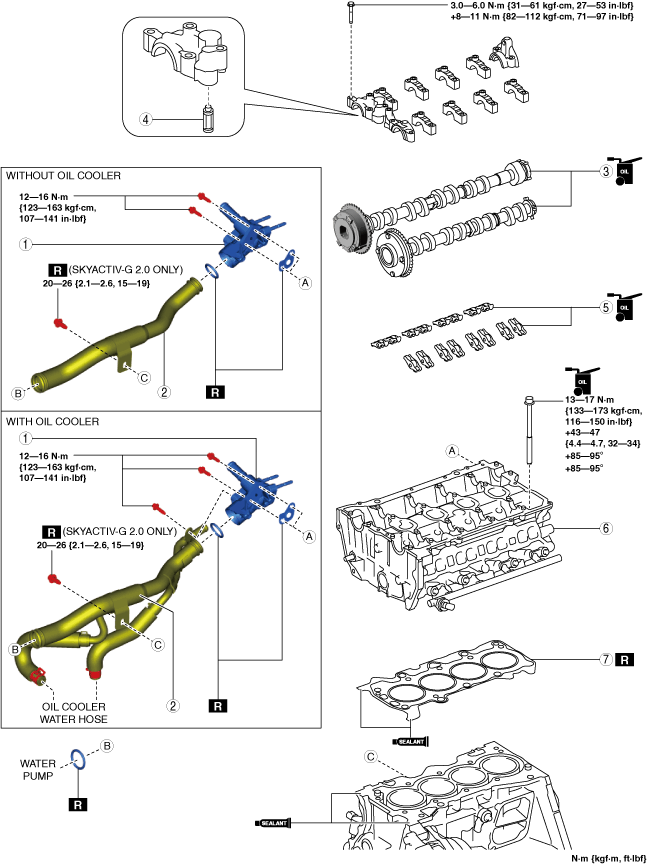
20.Remove in the order indicated in the table.
21.Install in the reverse order of removal.
22.Refill with the specified type and amount of the engine oil. (See ENGINE OIL REPLACEMENT [SKYACTIV-G (WITHOUT CYLINDER DEACTIVATION (US))].)
23.Refill the engine coolant. (See ENGINE COOLANT REPLACEMENT [SKYACTIV-G (WITH CYLINDER DEACTIVATION (US))].)
24.Start the engine, and inspect and adjust the following:
-
• Leakage of engine oil, engine coolant.• Runout and contact of pulley and belt.• Ignition timing, idle speed and idle mixture. (See ENGINE TUNE-UP [SKYACTIV-G (WITH CYLINDER DEACTIVATION (US))].)• Compression pressure (See COMPRESSION INSPECTION [SKYACTIV-G (WITHOUT CYLINDER DEACTIVATION (US))].)
am3zzw00024904
|
|
1
|
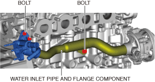
Flange
|
|
2
|
Water inlet pipe
|
|
3
|
Camshaft
(See Camshaft Removal Note.)
(See Camshaft Installation Note.)
|
|
4
|
OCV oil filter
|
|
5
|
Rocker arm
(See Rocker Arm Removal Note.)
(See Rocker Arm Installation Note.)
|
|
6
|
Cylinder head
(See Cylinder Head Removal Note.)
|
|
7
|
Cylinder head gasket
|
Camshaft Removal Note
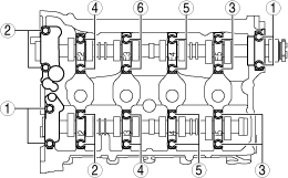
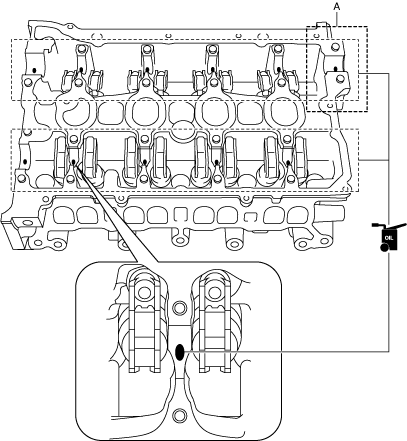
1.Loosen the camshaft cap installation bolts in a few passes in the order shown in the figure and remove the camshaft caps.
am6xuw00006678
|
2.Remove the camshafts.
Rocker Arm Removal Note
1.Keep the rocker arms in the order of removal to enable reassembly in their original positions.
Cylinder Head Removal Note
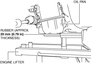
1.Temporarily install the oil pan to support the engine from under the vehicle.
-
Caution
-
• To prevent deformation of the oil pan, support the engine using the following methods.
-
― When using an engine lifter, insert rubber of appropriate size (approx. 20 mm {0.79 in} thickness) between the engine lifter and the oil pan to support the oil pan.
-
― When using a garage jack, place rubber of appropriate size (approx. 20 mm {0.79 in} thickness) on a batten which is large enough to cover the oil pan to support the oil pan.
-
2.Support the engine (oil pan) using a commercially available engine lifter or garage jack.
am6xuw00007883
|
3.Remove the chain on the SST that suspended the engine and set it aside.
4.Loosen the cylinder head installation bolts in two or three passes in the order shown in the figure and remove them.
am3uuw00008817
|
5.Remove the cylinder head.
Cylinder Head Installation Note
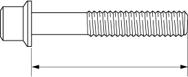
1.Measure the length of the cylinder head bolt.
-
• If it exceeds the maximum specification, replace the cylinder head bolt.
 amxzzw00003984
-
Standard cylinder head bolt length
-
145.2—145.8 mm {5.717—5.740 in}
-
Maximum cylinder head bolt length
-
146.5 mm {5.767 in}
2.When a cylinder head bolt is reused, apply engine oil to any part of the following:
-
• Bolt seating surface• Cylinder head seating surface
-
Caution
-
• Completely remove oil, dirt, and silicone sealant adhering to the cylinder head gasket contacting surfaces. Otherwise, a sealing malfunction may occur.
3.Completely remove any oil, dirt, and silicone sealant adhering to the cylinder block.
-
Caution
-
• Be aware of the following points, otherwise a sealing malfunction may occur due to hardening of the silicone sealant.
-
― Set cylinder head on cylinder block within 10 min after silicone sealant is applied― After setting cylinder head, tighten cylinder head bolts immediately
-
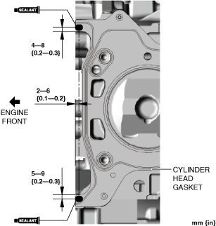
4.Apply silicone sealant (TB1217D or equivalent) to the areas shown in the figure.
SKYACTIV-G 2.0
am3zzw00024905
|
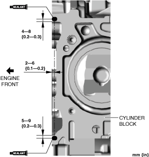
-
Silicone sealant application diameter
-
5—10 mm {0.2—0.3 in}
SKYACTIV-G 2.5
am3zzw00019917
|
-
Silicone sealant application diameter
-
5—10 mm {0.2—0.3 in}
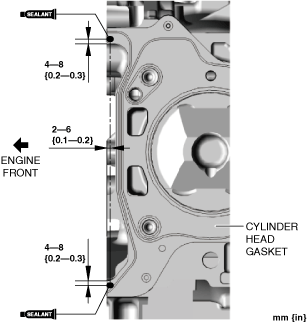
5.Install a new cylinder head gasket to the cylinder block.
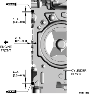
6.Apply silicone sealant (TB1217D or equivalent) to the areas shown in the figure.
SKYACTIV-G 2.0
am3zzw00024906
|
-
Silicone sealant application diameter
-
5—10 mm {0.2—0.3 in}
SKYACTIV-G 2.5
am3zzw00019920
|
-
Silicone sealant application diameter
-
5—10 mm {0.2—0.3 in}
7.Set the cylinder head on the cylinder block.
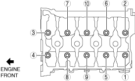
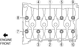
8.Tighten the cylinder head bolts in the order shown in the following 4 steps.
am3uuw00008818
|
9.Install the chain for the SST which was set aside and secure the engine.
10.Remove the engine lifter or garage jack.
11.Remove the temporarily assembled oil pan.
Rocker Arm Installation Note
1.Apply engine oil to the HLAs and the end of the valve stems.
am3uuw00008819
|
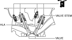
2.Install the rocker arms to the same positions as before removal.
Camshaft Installation Note
1.Apply SAE 90 gear oil or equivalent, or engine oil to the positions shown in the figure.
-
Caution
-
• Apply 0.05 ml {0.05 cc, 0.003 in 3} or less of oil to area A in the figure.
am2zzw00011199
|
2.Apply gear oil (SAE 90 or equivalent) or engine oil to the thrust surface (both surfaces front and back) of the front journal on each camshaft.
-
Caution
-
• Be careful not to let oil adheres the engine front cover installation surface. If oil adheres to the engine front cover installation surface, a sealing malfunction may occur when the engine front cover is installed.• If oil adheres to the engine front cover installation surface, remove any oil completely.
-
Note
-
• If oil is applied to the front camshaft cap, oil should not be applied to the thrust surface of the front journal.
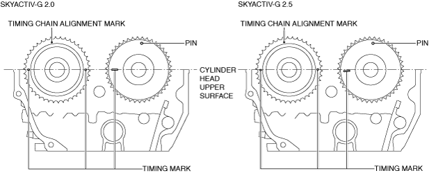
3.Install the camshaft with cylinder No.1 cam aligned to the TDC position as shown in the figure.
am3zzw00024907
|
4.Apply SAE 90 gear oil or equivalent, or engine oil to the central area of each journal on the camshaft.
am6xuw00006680
|
5.Apply SAE 90 gear oil or equivalent, or engine oil to the thrust surface of the front camshaft cap.
-
Caution
-
• Be careful not to let oil adheres the engine front cover installation surface. If oil adheres to the engine front cover installation surface, a sealing malfunction may occur when the engine front cover is installed.• If oil adheres to the engine front cover installation surface, remove any oil completely.
-
Note
-
• If oil is applied to the front journal thrust surface of each camshaft, oil should not be applied to the front camshaft cap.
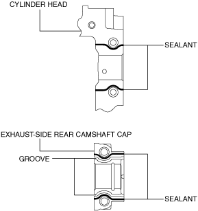
6.Apply sealant (LOCTITE 962T or equivalent) to the rear camshaft cap installation area on the exhaust side of the cylinder head or the rear camshaft cap on the exhaust side.
-
Note
-
• To prevent engine oil leakage, apply sealant to the rear camshaft cap installation area on the exhaust side or the rear camshaft caps on the exhaust side of the cylinder head, and seal the journal.
am2zzw00011072
|
-
Caution
-
• Do not spill sealant on the journal.
-
Sealant agent bead width
-
1—3 mm {0.04—0.11 in}
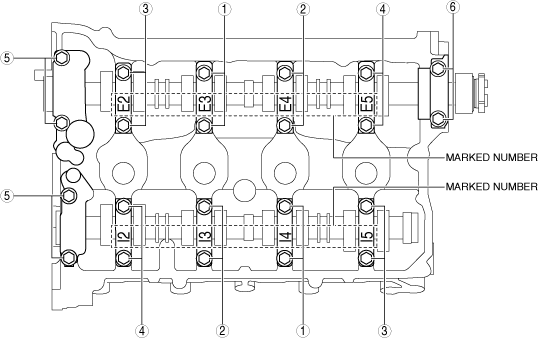
7.Install the camshaft caps in the marked number order, and temporarily tighten the camshaft cap installation bolts in two or three passes evenly.
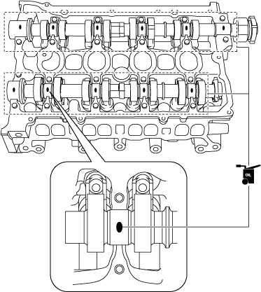
8.Tighten the camshaft cap installation bolts in two steps in the order shown in the figure.
am3uuw00008824
|
Water Inlet Pipe and Flange Installation Note
-
Caution
-
• Be aware of the following points, otherwise engine coolant leakage could result.
-
― Do not allow oil (such as engine oil, ATF) to contact O-ring― Do not damage O-rings
-
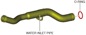
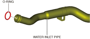
1.Apply engine coolant to a new O-ring (water pump side).
2.Install the O-ring to the water inlet pipe.
am3zzw00031750
|
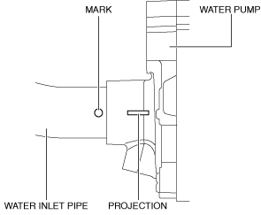
3.Insert the water inlet pipe into the water pump so that the marked position is aligned with the projection position.
ac5wzw00011077
|
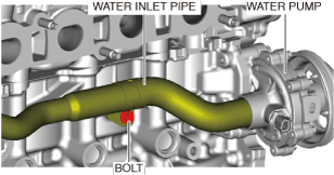
4.Temporarily tighten the bolt shown in the figure.
am6xuw00010491
|
5.Apply engine coolant to a new O-ring (flange side).
6.Install the O-ring to the water inlet pipe.
am3zzw00031751
|
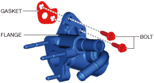
7.Assemble the flange, gasket and bolts.
am3zzw00031752
|
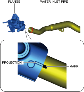
8.Assemble the water inlet pipe and the flange so that the marked position is aligned with the projection position.
ac5wzw00011340
|
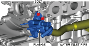
9.Temporarily tighten the bolt shown in the figure.
ac5wzw00011575
|
10.Tighten the bolts shown in the figure.
am3zzw00031753
|