WILL NOT CRANK [SKYACTIV-G (US)]
WILL NOT CRANK [SKYACTIV-G (US)]
SM2565583
id0103s48890s6
|
Troubleshooting item |
Will not crank |
|
|---|---|---|
|
Description
|
• Starter does not work.
|
|
|
Possible cause
|
• Battery malfunction
• Fuse malfunction
• Poor connection of push button start connector
• Instrument cluster or related wiring harness malfunction
• Immobilizer system malfunction
• PCM continuous memory DTC is stored
• Open circuit in PCM power supply circuit
• Open circuit in main relay control circuit
• CAN communication line malfunction between data link connector-2 and PCM
• Main relay malfunction (stuck open)
• Open or poor ground circuit
• Poor connection of vehicle body ground
• Starter relay malfunction
• Starter interlock switch and related wiring harness malfunction (MTX)
• TCM and related wiring harness malfunction (ATX)
• Short to ground in starter relay control circuit
• Open circuit in starter relay control circuit
• Short to ground or open circuit in starter relay power supply circuit
• Short to ground or open circuit in starter power supply circuit
• Starting system malfunction
• Following circuit and/or connector malfunction:
• Seized engine, flywheel (MTX) or drive plate (ATX)
• Engine damage during compression due to liquid (such as water, fuel, or engine oil) penetration into cylinder
|
|
 |
||
 |
||
 |
||
 |
||
 |
||
 |
 |
|
 |
 |
|
 |
 |
|
 |
 |
|
 |
||
 |
||
 |
||
 |
||
 |
||
Diagnostic Procedure
|
Step |
Inspection |
Results |
Action |
|---|---|---|---|
|
1
|
INSPECT POWER SUPPLY
• Access the VPWR PID using the M-MDS. (See PID/DATA MONITOR INSPECTION.)
• Verify the VPWR PID value.
• Is the VPWR PID value B+?
|
Yes
|
Go to the next step.
|
|
No
|
Inspect the following:
• Battery connection
• Battery condition (See BATTERY INSPECTION [(US)].)
• Fuse (See BLOWN FUSES [SKYACTIV-G (US)].)
|
||
|
2
|
DETERMINE IF MALFUNCTION CAUSE IS IMMOBILIZER SYSTEM OR OTHER
• Are any of the following conditions present?
|
Yes
|
Both conditions present:
• Go to Step 5.
|
|
No
|
Either or other condition present:
• Go to the next step.
|
||
|
3
|
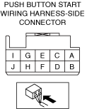
INSPECT PUSH BUTTON START CONNECTOR CONNECTION
• Inspect the connection of push button start connector.
• Is the push button start connector securely connected to the coil antenna?
|
Yes
|
Go to the next step.
|
|
No
|
Reconnect the push button start securely, then repeat from Step 1.
|
||
|
4
|
DETERMINE IF MALFUNCTION CAUSE IS INSTRUMENT CLUSTER OR OTHER
• Switch the ignition ON (engine off).
• Does the security indicator light flash?
|
Yes
|
Go to the next step.
|
|
No
|
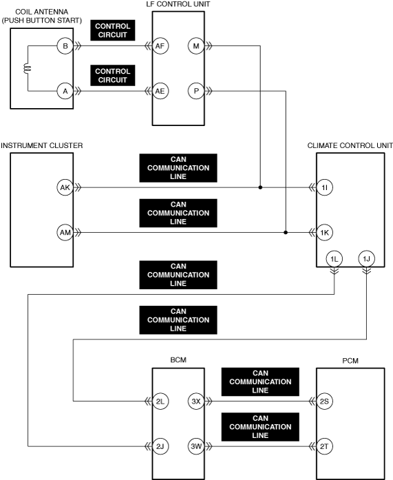
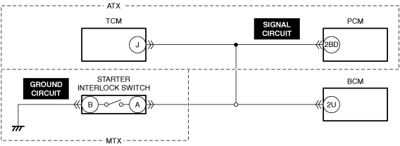
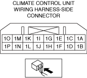
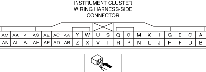
Inspect the wiring harness between the following terminals:
• Instrument cluster terminal AK—Climate control unit terminal 1I
• Instrument cluster terminal AM—Climate control unit terminal 1K
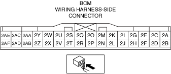
• Climate control unit terminal 1J—Body control module (BCM) terminal 2L
• Climate control unit terminal 1L—Body control module (BCM) terminal 2J
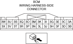
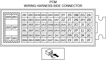
• Body control module (BCM) terminal 3X—PCM terminal 2S
• Body control module (BCM) terminal 3W—PCM terminal 2T
• Inspect the instrument cluster (See INSTRUMENT CLUSTER INSPECTION [(US)].)
|
||
|
5
|
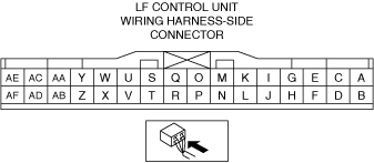
VERIFY IMMOBILIZER SYSTEM (LF CONTROL UNIT) DTC
• Perform the DTC inspection for the body control module (BCM). (See DTC INSPECTION.)
• Are any DTCs displayed?
|
Yes
|
Repair the malfunctioning location according to the applicable DTC troubleshooting.
|
|
No
|
Go to the next step.
|
||
|
6
|
VERIFY PCM DTC
• Perform the DTC inspection for the PCM. (See DTC INSPECTION.)
• Are any continuous memory DTCs present?
|
Yes
|
Continuous memory DTC is displayed:
• Repair the malfunctioning location according to the applicable DTC troubleshooting. (See DTC TABLE [PCM (SKYACTIV-G (US))].)
Communication error message is displayed:
• Go to the next step.
|
|
No
|
Go to Step 12.
|
||
|
7
|
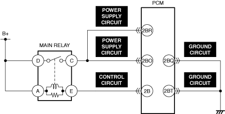
INSPECT MAIN RELAY CONTROL CIRCUIT FOR OPEN CIRCUIT
• Inspect the applicable circuit for open circuit. (See CIRCUIT INSPECTION.)
• Is the circuit normal?
|
Yes
|
Go to the next step.
|
|
No
|
Repair or replace the malfunctioning location and perform the repair completion verification.
|
||
|
8
|
INSPECT PCM POWER SUPPLY CIRCUIT FOR OPEN CIRCUIT
• Inspect the applicable circuit for open circuit. (See CIRCUIT INSPECTION.)
• Is the circuit normal?
|
Yes
|
Go to the next step.
|
|
No
|
Repair or replace the malfunctioning location and perform the repair completion verification.
|
||
|
9
|
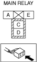
INSPECT MAIN RELAY FOR MALFUNCTION
• Inspect the applicable part. (See RELAY INSPECTION.)
• Is the part normal?
|
Yes
|
Go to the next step.
|
|
No
|
Repair or replace the malfunctioning location and perform the repair completion verification.
(See RELAY LOCATION [(US)].)
|
||
|
10
|
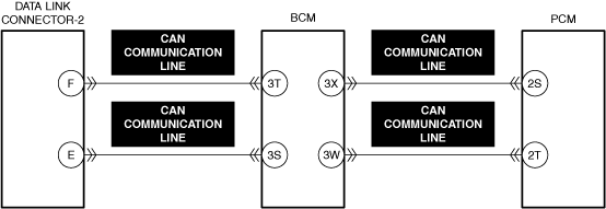
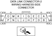
INSPECT CAN COMMUNICATION LINE BETWEEN DLC-2 AND PCM FOR OPEN CIRCUIT
• Inspect the applicable circuit for open circuit. (See CIRCUIT INSPECTION.)
• Is the circuit normal?
|
Yes
|
Go to the next step.
|
|
No
|
Repair or replace the malfunctioning location and perform the repair completion verification.
|
||
|
11
|
INSPECT PCM GROUND CIRCUIT FOR OPEN CIRCUIT
• Inspect the applicable circuit for open circuit. (See CIRCUIT INSPECTION.)
• Is the circuit normal?
|
Yes
|
Go to the next step.
|
|
No
|
Repair or replace the malfunctioning location and perform the repair completion verification.
|
||
|
12
|
DETERMINE IF MALFUNCTION CAUSE IS STARTER RELAY CONTROL CIRCUIT OR OTHER
• Crank the engine.
• Is a clicking sound heard from the starter relay?
|
Yes
|
Go to Step 23.
|
|
No
|
ATX:
• Go to Step 16.
MTX:
• Go to the next step.
|
||
|
13
|
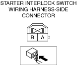
DETERMINE IF MALFUNCTION CAUSE IS STARTER INTERLOCK SWITCH OR OTHER
• Switch the ignition off.
• Short the starter interlock switch terminals A and B (wiring harness-side) using a jumper wire.
• Crank the engine.
• Does the engine start?
|
Yes
|
Inspect the starter interlock switch.
• If there is any malfunction:
• If there is no malfunction:
|
|
No
|
Go to the next step.
|
||
|
14
|
INSPECT STARTER INTERLOCK SWITCH CONNECTOR FOR MALFUNCTION
• Inspect the applicable connector and terminal. (See CONNECTOR INSPECTION.)
• Are the connector and terminal normal?
|
Yes
|
Go to the next step.
|
|
No
|
Repair or replace the malfunctioning location and perform the repair completion verification.
|
||
|
15
|
INSPECT STARTER INTERLOCK SWITCH GROUND CIRCUIT FOR OPEN CIRCUIT
• Inspect the applicable circuit for open circuit. (See CIRCUIT INSPECTION.)
• Is the circuit normal?
|
Yes
|
Go to Step 18.
|
|
No
|
Repair or replace the malfunctioning location and perform the repair completion verification.
|
||
|
16
|
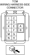
INSPECT TCM CONNECTOR FOR MALFUNCTION
• Inspect the applicable connector and terminal. (See CONNECTOR INSPECTION.)
• Are the connector and terminal normal?
|
Yes
|
Go to the next step.
|
|
No
|
Repair or replace the malfunctioning location and perform the repair completion verification.
|
||
|
17
|
INSPECT TCM SIGNAL CIRCUIT FOR OPEN CIRCUIT
• Inspect the applicable circuit for open circuit. (See CIRCUIT INSPECTION.)
• Is the circuit normal?
|
Yes
|
Go to the next step.
|
|
No
|
Repair or replace the malfunctioning location and perform the repair completion verification.
|
||
|
18
|
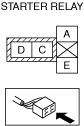
INSPECT STARTER RELAY FOR MALFUNCTION
• Inspect the applicable part. (See RELAY INSPECTION.)
• Is the part normal?
|
Yes
|
Go to the next step.
|
|
No
|
Repair or replace the malfunctioning location and perform the repair completion verification.
(See RELAY LOCATION [(US)].)
|
||
|
19
|
INSPECT BODY CONTROL MODULE (BCM) CONNECTOR FOR MALFUNCTION
• Inspect the applicable connector and terminal. (See CONNECTOR INSPECTION.)
• Are the connector and terminal normal?
|
Yes
|
Go to the next step.
|
|
No
|
Repair or replace the malfunctioning location and perform the repair completion verification.
|
||
|
20
|
INSPECT PCM CONNECTOR FOR MALFUNCTION
• Inspect the applicable connector and terminal. (See CONNECTOR INSPECTION.)
• Are the connector and terminal normal?
|
Yes
|
Go to the next step.
|
|
No
|
Repair or replace the malfunctioning location and perform the repair completion verification.
|
||
|
21
|
INSPECT STARTER RELAY CONTROL CIRCUIT FOR SHORT TO GROUND
• Inspect the applicable circuit for a short to ground. (See CIRCUIT INSPECTION.)
• Is the circuit normal?
|
Yes
|
Go to the next step.
|
|
No
|
Repair or replace the malfunctioning location and perform the repair completion verification.
|
||
|
22
|
INSPECT STARTER RELAY CONTROL CIRCUIT FOR OPEN CIRCUIT
• Inspect the applicable circuit for open circuit. (See CIRCUIT INSPECTION.)
• Is the circuit normal?
|
Yes
|
Inspect the body control module (BCM).
• If there is any malfunction:
• If there is no malfunction:
|
|
No
|
Repair or replace the malfunctioning location and perform the repair completion verification.
|
||
|
23
|
INSPECT STARTER CONNECTOR FOR MALFUNCTION
• Inspect the applicable connector and terminal. (See CONNECTOR INSPECTION.)
• Are the connector and terminal normal?
|
Yes
|
Go to the next step.
|
|
No
|
Repair or replace the malfunctioning location and perform the repair completion verification.
|
||
|
24
|
DETERMINE IF MALFUNCTION CAUSE IS STARTER OR OTHER
• Verify that the starter connector is disconnected.
• Crank the engine.
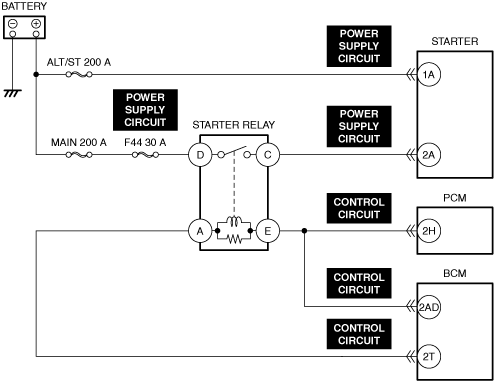
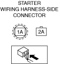
• Measure the voltage at the starter terminal 2A (wiring harness-side)
• Is the voltage B+?
|
Yes
|
Go to Step 28.
|
|
No
|
Go to the next step.
|
||
|
25
|
INSPECT STARTER RELAY POWER SUPPLY CIRCUIT FOR SHORT TO GROUND AND OPEN CIRCUIT
• Inspect the power supply circuit for an open circuit and short to ground. (See CIRCUIT INSPECTION.)
• Is the circuit normal?
|
Yes
|
Go to the next step.
|
|
No
|
Repair or replace the malfunctioning location and perform the repair completion verification.
|
||
|
26
|
INSPECT POWER SUPPLY CIRCUIT BETWEEN STARTER RELAY AND STARTER FOR SHORT TO GROUND
• Inspect the applicable circuit for a short to ground. (See CIRCUIT INSPECTION.)
• Is the circuit normal?
|
Yes
|
Go to the next step.
|
|
No
|
Repair or replace the malfunctioning location and perform the repair completion verification.
|
||
|
27
|
INSPECT POWER SUPPLY CIRCUIT BETWEEN STARTER RELAY AND STARTER FOR OPEN CIRCUIT
• Inspect the applicable circuit for open circuit. (See CIRCUIT INSPECTION.)
• Is the circuit normal?
|
Yes
|
Go to the next step.
|
|
No
|
Repair or replace the malfunctioning location and perform the repair completion verification.
|
||
|
28
|
INSPECT POWER SUPPLY CIRCUIT BETWEEN BATTERY AND STARTER FOR SHORT TO GROUND AND OPEN CIRCUIT
• Inspect the power supply circuit for an open circuit and short to ground. (See CIRCUIT INSPECTION.)
• Is the circuit normal?
|
Yes
|
Go to the next step.
|
|
No
|
Repair or replace the malfunctioning location and perform the repair completion verification.
|
||
|
29
|
INSPECT STARTER FOR MALFUNCTION
• Inspect the applicable part. (See STARTER INSPECTION [SKYACTIV-G (WITH CYLINDER DEACTIVATION (US))].) (See STARTER INSPECTION [SKYACTIV-G (WITHOUT CYLINDER DEACTIVATION (US))].)
• Is the part normal?
|
Yes
|
Go to the next step.
|
|
No
|
Repair or replace the malfunctioning location and perform the repair completion verification.
|
||
|
30
|
INSPECT IMMOBILIZER SYSTEM RELATED CIRCUIT
• Inspect the following wiring harness and connectors:
• Is there any malfunction?
|
Yes
|
Repair or replace the malfunctioning location and perform the repair completion verification.
|
|
No
|
Go to the next step.
|
||
|
31
|
VERIFY PRESENT MALFUNCTION DTC
• Perform the KOEO self test. (See DTC INSPECTION.)
• Are any DTCs displayed?
|
Yes
|
Repair the malfunctioning location according to the applicable DTC troubleshooting.
|
|
No
|
Go to the next step.
|
||
|
32
|
DETERMINE IF MALFUNCTION CAUSE IS BASE ENGINE OR OTHER
• Inspect for a seized flywheel (MTX) or drive plate (ATX).
• Is the flywheel (MTX) or drive plate (ATX) seized?
|
Yes
|
Repair or replace the malfunctioning location and perform the repair completion verification.
|
|
No
|
Base engine malfunction or engine damage during compression due to liquid (such as water, fuel, or engine oil) penetration into cylinder.
• Overhaul or replace the engine and perform the repair completion verification.
|
||
|
Repair completion verification 1
|
VERIFY THAT VEHICLE IS REPAIRED
• Install/connect the part removed/disconnected during the troubleshooting procedure.
• Has the malfunction symptom been eliminated?
|
Yes
|
Complete the symptom troubleshooting. (Explain contents of repair to customer)
|
|
No
|
Refer to the controller area network (CAN) malfunction diagnosis flow to inspect for a CAN communication error.
• If the CAN communication is normal, perform the diagnosis from Step 1.
|
||
|
Repair completion verification 2
|
VERIFY IF MALFUNCTION IS CAUSED BY NOT PERFORMING PCM REPROGRAMMING
• Verify repair information and verify that there is a new calibration in the PCM.
• Is there a new calibration in the PCM?
|
Yes
|
Perform the PCM reprogramming and verify if the malfunction symptom was corrected.
• If the malfunction recurs, replace the PCM. (See PCM REMOVAL/INSTALLATION [SKYACTIV-G (WITH CYLINDER DEACTIVATION (US))].) (See PCM REMOVAL/INSTALLATION [SKYACTIV-G (WITHOUT CYLINDER DEACTIVATION (US))].)
|
|
No
|
Replace the PCM.
|