DTC P19A0:00 [PCM (SKYACTIV-G (US))]
DTC P19A0:00 [PCM (SKYACTIV-G (US))]
SM2565517
id0102t40106u0
-
Note
-
• To determine the malfunctioning part, proceed with the diagnostics from “Function Inspection Using M-MDS”.
Details On DTCs
|
Description |
Revolution sensor signal: correlation problem |
||
|---|---|---|---|
|
Detection condition
|
Determination conditions
|
• The difference between the engine speed and the clutch disc rotation speed is the specified value or more during gear engagement.
|
|
|
Preconditions
|
• Under load
|
||
|
Malfunction determination period
|
• 5 s period
|
||
|
Drive cycle
|
• 1
|
||
|
Self test type
|
• CMDTC self test
|
||
|
Sensor used
|
• Revolution sensor
• CKP sensor
• PCM
|
||
|
Fail-safe function
|
• Not applicable
|
||
|
Vehicle status when DTCs are output
|
• A vehicle shock may occur due to engine powertrain vibration.
|
||
|
Possible cause
|
• Revolution sensor connector or terminals malfunction
• Short to ground in any of the following revolution sensor circuits.
• PCM connector or terminals malfunction
• Short to power supply in any of the following revolution sensor circuits.
• Short circuit between any of the following revolution sensor circuits.
• Open circuit in any of the following revolution sensor circuits.
• Revolution sensor incorrect installation
• Revolution sensor malfunction
• Manual transaxle malfunction
• PCM malfunction
|
||
 |
|||
 |
|||
 |
|||
Function Explanation (DTC Detection Outline)
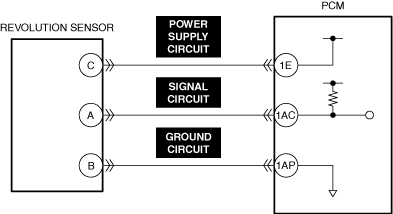
• The PCM calculates the rotation speed of the clutch based on the signal input from the revolution sensor. The engine speed and clutch rotation speed match while the clutch is engaged and the vehicle is being driven. However, if the difference between the engine speed and clutch rotation speed is the specified value or more while the clutch is engaged and the vehicle is being driven, the PCM determines a malfunction in the revolution sensor and stores a DTC.
Repeatability Verification Procedure
1. Start the engine.
2. Accelerate and drive the vehicle while maintaining the speed for 1 min with the clutch pedal released (clutch engaged).
PID Item/Simulation Item Used In Diagnosis
• Not applicable
Function Inspection Using M-MDS
|
Step |
Inspection |
Results |
Action |
|---|---|---|---|
|
1
|
PURPOSE: VERIFY RELATED REPAIR INFORMATION OR SERVICE INFORMATION AVAILABILITY
• Verify related Service Bulletins, on-line repair information, or Service Information availability.
• Is any related Information available?
|
Yes
|
Perform repair or diagnosis according to the available information.
• If the vehicle is not repaired, go to the next step.
|
|
No
|
Go to the next step.
|
||
|
2
|
PURPOSE: RECORD VEHICLE STATUS WHEN DTC WAS DETECTED TO UTILIZE WITH REPEATABILITY VERIFICATION
• Record the freeze frame data/snapshot data.
|
—
|
Go to Troubleshooting Diagnostic Procedure to perform the procedure from Step 1.
|
Troubleshooting Diagnostic Procedure
Intention of troubleshooting procedure
• Step 1—6
-
― Perform an inspection of the connectors and wiring harnesses between the revolution sensor and the PCM.
• Step 7
-
― Verify the revolution sensor installation condition.
• Step 8
-
― Perform a unit inspection of the revolution sensor.
• Step 9
-
― Inspect the manual transaxle for a malfunction depending on repeatability.
• Repair completion verification
-
― Verify that the primary malfunction is resolved and there are no other malfunctions.
|
Step |
Inspection |
Results |
Action |
|---|---|---|---|
|
1
|
PURPOSE: INSPECT REVOLUTION SENSOR CONNECTOR FOR MALFUNCTION
• Inspect the applicable connector and terminal. (See CONNECTOR INSPECTION.)
• Are the connector and terminal normal?
|
Yes
|
Go to the next step.
|
|
No
|
Repair or replace the malfunctioning location and perform the repair completion verification 1.
|
||
|
2
|
PURPOSE: INSPECT REVOLUTION SENSOR POWER SUPPLY CIRCUITS, SIGNAL CIRCUITS, AND GROUND CIRCUITS FOR SHORT TO GROUND
• Inspect the applicable circuit for a short to ground. (See CIRCUIT INSPECTION.)
• Is the circuit normal?
|
Yes
|
Go to the next step.
|
|
No
|
Repair or replace the malfunctioning location and perform the repair completion verification 1.
|
||
|
3
|
PURPOSE: INSPECT PCM CONNECTOR FOR MALFUNCTION
• Inspect the applicable connector and terminal. (See CONNECTOR INSPECTION.)
• Are the connector and terminal normal?
|
Yes
|
Go to the next step.
|
|
No
|
Repair or replace the malfunctioning location and perform the repair completion verification 1.
|
||
|
4
|
PURPOSE: INSPECT REVOLUTION SENSOR POWER SUPPLY CIRCUITS, SIGNAL CIRCUITS, AND GROUND CIRCUITS FOR SHORT TO POWER SUPPLY
• Inspect the applicable circuit for a short to power supply. (See CIRCUIT INSPECTION.)
• Is the circuit normal?
|
Yes
|
Go to the next step.
|
|
No
|
Repair or replace the malfunctioning location and perform the repair completion verification 1.
|
||
|
5
|
PURPOSE: INSPECT REVOLUTION SENSOR POWER SUPPLY CIRCUITS, SIGNAL CIRCUITS, AND GROUND CIRCUITS FOR SHORT CIRCUIT
• Inspect the applicable circuits for a short circuit. (See CIRCUIT INSPECTION.)
• Is the circuit normal?
|
Yes
|
Go to the next step.
|
|
No
|
Repair or replace the malfunctioning location and perform the repair completion verification 1.
|
||
|
6
|
PURPOSE: INSPECT REVOLUTION SENSOR POWER SUPPLY CIRCUITS, SIGNAL CIRCUITS, AND GROUND CIRCUITS FOR OPEN CIRCUIT
• Inspect the applicable circuit for open circuit. (See CIRCUIT INSPECTION.)
• Is the circuit normal?
|
Yes
|
Go to the next step.
|
|
No
|
Repair or replace the malfunctioning location and perform the repair completion verification 1.
|
||
|
7
|
PURPOSE: VERIFY IF REVOLUTION SENSOR IS INSTALLED CORRECTLY
• Verify the revolution sensor installation condition. (See REVOLUTION SENSOR REMOVAL/INSTALLATION [C66M-R].)
• Is the installation condition normal?
|
Yes
|
Go to the next step.
|
|
No
|
Correctly install the revolution sensor and perform the repair completion verification 1.
|
||
|
8
|
PURPOSE: INSPECT REVOLUTION SENSOR FOR MALFUNCTION
• Inspect the applicable part. (See REVOLUTION SENSOR INSPECTION [SKYACTIV-G (WITH CYLINDER DEACTIVATION (US))].) (See REVOLUTION SENSOR INSPECTION [SKYACTIV-G (WITHOUT CYLINDER DEACTIVATION (US))].)
• Is the part normal?
|
Yes
|
Go to the next step.
|
|
No
|
Repair or replace the malfunctioning location and perform the repair completion verification 1.
|
||
|
9
|
PURPOSE: INSPECT MANUAL TRANSAXLE FOR MALFUNCTION DEPENDING ON REPEATABILITY
• Install/connect the part removed/disconnected during the troubleshooting procedure.
• Clear the DTC recorded in the memory. (See CLEARING DTC.)
• Replicate the vehicle conditions at the time the DTC was detected using the following procedure.
• Perform the DTC inspection for the PCM. (See DTC INSPECTION.)
• Is the same Pending DTC present?
|
Yes
|
Replace the manual transaxle and perform the repair completion verification 1.
|
|
No
|
Go to repair completion verification 2.
|
||
|
Repair completion verification 1
|
PURPOSE: VERIFY THAT VEHICLE IS REPAIRED
• Install/connect the part removed/disconnected during the troubleshooting procedure.
• Clear the DTC recorded in the memory. (See CLEARING DTC.)
• Replicate the vehicle conditions at the time the DTC was detected using the following procedure.
• Perform the DTC inspection for the PCM. (See DTC INSPECTION.)
• Is the same Pending DTC present?
|
Yes
|
Refer to the controller area network (CAN) malfunction diagnosis flow to inspect for a CAN communication error.
If the CAN communication is normal, perform the diagnosis from Step 1.
• If the malfunction recurs, replace the PCM, then go to the next step. (See PCM REMOVAL/INSTALLATION [SKYACTIV-G (WITH CYLINDER DEACTIVATION (US))].) (See PCM REMOVAL/INSTALLATION [SKYACTIV-G (WITHOUT CYLINDER DEACTIVATION (US))].)
|
|
No
|
Go to the next step.
|
||
|
Repair completion verification 2
|
PURPOSE: VERIFY IF OTHER DTCs DISPLAYED
• Perform the DTC inspection. (See DTC INSPECTION.)
• Are any other DTCs displayed?
|
Yes
|
Repair the malfunctioning location according to the applicable DTC troubleshooting.
|
|
No
|
DTC troubleshooting completed.
|