360°VIEW MONITOR SYSTEM AIMING
360°VIEW MONITOR SYSTEM AIMING
SM2337173
id152000010200
Special service tool (SST)
|
49 L067 006
Plumb bob
|
 |
49 JP04 001
Target marker
|
 |
Preparation Before Servicing
1.Empty the vehicle by having all occupants leave the vehicle and remove all the cargo except for the spare tire, jack and tools equipped on the vehicle.
2.Adjust the air pressure of each tire to the specified value. (See WHEEL AND TIRE SPECIFICATION [(US)].)
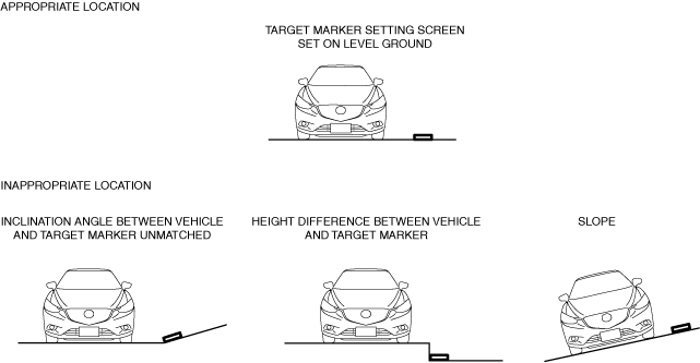
3.Move the vehicle to level ground.
-
Caution
-
• If the setting surface height and angle between the vehicle and the target marker differs, correct front camera aiming cannot be done. Perform the front camera aiming with the vehicle and target marker setting surface on level ground.• Level ground conditions must be within 2 degrees for the front and back, and right and left.• Do not move or shake the vehicle during aiming adjustment (such as riding in or opening a door).• Remove dust or dirt from the lens surface of the 4 cameras.• The voltage supplied to the 360° view monitor control module must be 9.5—15.5 V.• The aiming adjustment must be performed under approx. -30—60 °C {-22—140 °F} conditions.
 am3zzw00036900
4.Using the M-MDS, perform a DTC inspection for 360° view monitor unit and verify that no DTCs are displayed. (See DTC INSPECTION.)
-
Note
-
• If any DTCs are displayed, perform malfunction repair referring to the applicable DTC troubleshooting. (See DTC TABLE [360°VIEW MONITOR CONTROL MODULE (US)].) (See DTC TABLE [VEHICLE CONTROL MODULE (US)].)
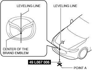
5.Adjust the SST so that it is aligned with the center of the brand emblem, determine the center position at the front of the vehicle, and mark the center position (point A) on the floor surface.
am3zzw00036901
|
-
Note
-
• The center of the brand emblem indicates the center position of the vehicle.
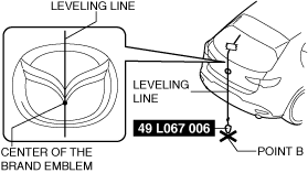
6.Adjust the SST so that it is aligned with the center of the brand emblem, determine the center position at the rear of the vehicle, and mark the center position (point B) on the floor surface.
am3zzw00036902
|
-
Note
-
• The center of the brand emblem indicates the center position of the vehicle.
7.Pull the leveling line towards the front and rear of the vehicle and adjust it so that it passes over points A and B.
-
Note
-
• Use a commercially-available leveling line.
am3zzw00036903
|
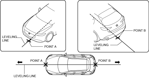
8.Secure the leveling line.
Selection of Procedure for 360° View Monitor System Aiming
-
Note
-
• For the front camera aiming, side camera aiming, and rear mount camera aiming, 1 set(1 set/2 targets) of the SST (49 JP04 001) are required.• For the 360° view monitor system aiming (batch aiming), 4 sets(1 set/2 targets) of the SST (49 JP04 001) are required. If 4 sets of the SST (49 JP04 001) is unavailable, perform the aiming for the 4 cameras individually.• When any of the following operations is performed, it is necessary to verify if the front camera aiming, side camera aiming, and rear mount camera aiming needs to be performed.
-
― Servicing requiring verification of necessity to perform front camera aiming
-
• Front camera removal/installation• Front bumper removal/installation
-
-
― Servicing requiring verification of necessity to perform side camera aiming
-
• Side camera removal/installation• Power outer mirror removal/installation• Lower outer mirror garnish removal/installation• Side turn light removal/installation• Front door removal/installation or adjustment
-
-
― Servicing requiring verification of necessity to perform rear mount camera aiming
-
• Rear mount camera removal/installation• Rear bumper removal/installation
-
-
|
Step |
Procedure |
Action after procedure |
|
|---|---|---|---|
|
1
|
Was the 360° view monitor control module replaced?
|
Yes
|
Go to step 4.
|
|
No
|
Go to the next step.
|
||
|
2
|
To determine if aiming is necessary or not, perform the 360° view monitor system screen display verification procedure.
Is it necessary to perform aiming?
|
Yes
|
Go to the next step.
|
|
No
|
Procedure is completed.
|
||
|
3
|
Which of the cameras requires aiming?
|
Front camera
|
Perform the front camera aiming and go to step 5.
|
|
Side camera
|
Perform the side camera aiming and go to step 5.
|
||
|
Rear mount camera
|
Perform the rear mount camera aiming and go to step 5.
|
||
|
4
|
For the 360° view monitor system aiming (batch aiming), 4 sets of the SST (49 JP04 001) are required.
Are 4 sets of the SST (49 JP04 001) available?
|
Yes
|
Perform the 360° view monitor system aiming (batch aiming) procedure and go to step 5.
|
|
No
|
Individually perform aiming for the camera requiring aiming, then go to Step 5.
|
||
|
5
|
Perform the 360° view monitor system screen display verification procedure.
Is 360° view monitor system aiming procedure needed?
|
Yes
|
Repeat Step 4.
|
|
No
|
Procedure is completed.
|
||
360° View Monitor System Screen Display Verification Procedure
1.Perform the preparation before servicing. (See Preparation Before Servicing.)
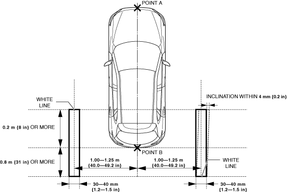
2.Position the white lines at the positions shown in the figure.
If all the cameras are verified
am3zzw00036904
|
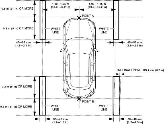
If the front camera is verified
am3zzw00036905
|

If the side camera is verified
am3zzw00036906
|

If the rear mount camera is verified
am3zzw00036907
|
-
Note
-
• Use paper of 10 mm {0.39 in} thickness or less, or tape for the white lines.
3.Close all the doors (front door, rear door) and the trunk lid (4SD)/liftgate (5HB).
4.Verify that the outer mirrors are unfolded.
5.Operate the electric parking brake.
6.Shift the selector lever to the P position. (ATX)
7.Shift the shift lever to the neutral position. (MTX)
8.Switch the ignition ON (engine off or on).
9.Display the screen of the 360° view monitor system in the center display by pressing the 360° view monitor switch.
-
Note
-
• If the projected vehicle path indication (yellow line) obscures the white lines, uncheck the check mark in the guide line display setting to turn the projected vehicle path indication off.am3zzw00036908

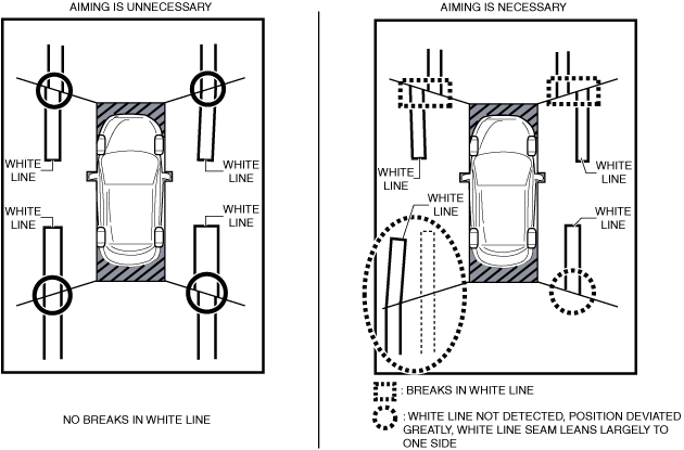
10.Verify that there are no breaks in the seams of the white lines in the display screen of the center display.
-
• If there are no breaks in the seams of the white lines, the 360° view monitor system aiming is completed.• If there are breaks in the seams of the white lines, perform the aiming procedure. (See 360° View Monitor System Aiming (Batch Aiming) Procedure.)• If the white lines cannot be found, a position has deviated, or the seams of the white lines lean largely to one side, return to Step 2 and verify the white line position.
ac8wzw00000988
|
360° View Monitor System Aiming (Batch Aiming) Procedure
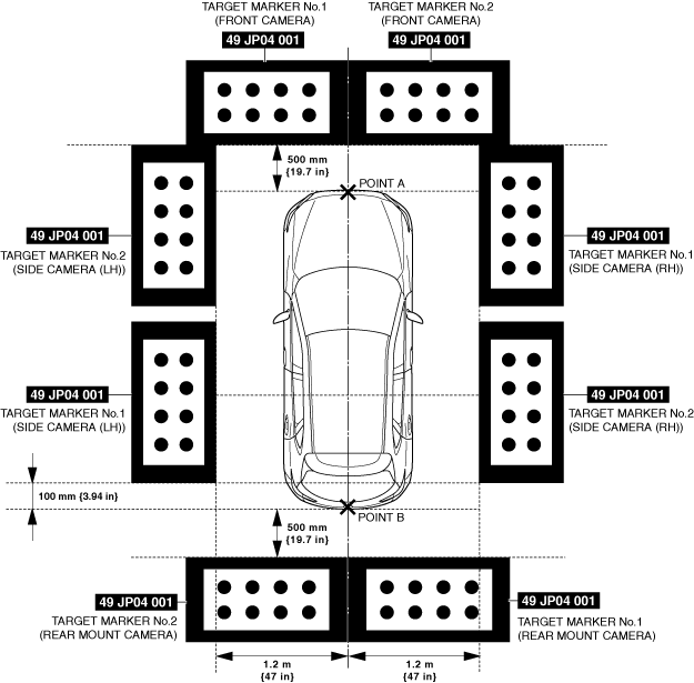
1.Position the SSTs at the positions shown in the figure.
am3zzw00036909
|
2.Connect the M-MDS to the DLC-2.
3.Close all the doors (front door, rear door) and the trunk lid (4SD)/liftgate (5HB).
4.Verify that the outer mirrors are unfolded.
5.Operate the electric parking brake.
6.Shift the selector lever to the P position. (ATX)
7.Shift the shift lever to the neutral position. (MTX)
8.After vehicle identification is completed, select the following from the M-MDS initial screen.
- (1)[Toolbox]
- (2)[Work Support]
- (3)[i-ACTIVSENSE]
- (4)[Static aiming]
- (5)[Static aiming for 360° View Monitor System]
9.Perform the 360° view monitor system aiming according to the directions on the M-MDS.
10.Verify the M-MDS display.
-
• If [Procedure completed successfully] is displayed
-
― The 360° view monitor system aiming is completed. Perform the 360° view monitor system screen display verification procedure. (See 360° View Monitor System Screen Display Verification Procedure.)
-
-
• If [Procedure not completed successfully] is displayed.
-
― Perform an inspection according to the following table for the error code procedure.― If an error code other than the error codes in the following table is displayed, verify the following and perform the 360° view monitor system aiming again if there is no malfunction, as there could be a communication error between the 360° view monitor unit and the diagnostic tester.
-
1. Is the battery positive voltage for the vehicle 8 V or more?2. Is the ignition switched to ACC or ON (engine off or on)?
-
-
|
Error code |
Detection Condition |
|---|---|
|
03
|
Target marker No.1 of rear mount camera is not detected
|
|
04
|
Target marker No.2 of rear mount camera is not detected
|
|
06
|
Target marker No.1 of side camera (LH) is not detected
|
|
07
|
Target marker No.2 of side camera (LH) is not detected
|
|
09
|
Target marker No.1 of front camera is not detected
|
|
0A
|
Target marker No.2 of front camera is not detected
|
|
0C
|
Target marker No.1 of side camera (RH) is not detected
|
|
0D
|
Target marker No.2 of side camera (RH) is not detected
|
|
10
|
Input vehicle value exceeds specification
|
|
12
|
Because the following aiming implementation conditions are not met, the aiming is not completed.
• Vehicle stopped
• All doors (front door, rear door) and trunk lid (4SD)/liftgate (5HB) closed
• Outer mirrors unfolded
• Electric parking brake operated
• Selector lever is in P position (ATX)
• Shift lever is in neutral position (MTX)
|
|
15
|
Aiming is not possible due to malfunction in 360° view monitor control module
|
|
16
|
360° view monitor control module cannot receive rear mount camera images
|
|
17
|
360° view monitor control module cannot receive side camera (LH) images
|
|
18
|
360° view monitor control module cannot receive front camera images
|
|
19
|
360° view monitor control module cannot receive side camera (RH) images
|
|
1A
|
Power supply to camera insufficient
|
Error code 03/04/06/07/09/0A/0C/0D/10
|
Step |
Inspection |
Action |
|
|---|---|---|---|
|
1
|
VERIFY TARGET MARKER SETTING ENVIRONMENT AND POSITION
• Verify the following.
• Display the screen of the 360° view monitor system in the center display by pressing the 360° view monitor switch.
• Is there a malfunction?
|
Yes
|
Repair the malfunctioning location and go to the next step.
|
|
No
|
Go to the next step.
|
||
|
2
|
PERFORM 360° VIEW MONITOR SYSTEM AIMING
• Perform the 360° view monitor system aiming.
• Was the 360° view monitor system aiming procedure completed correctly?
|
Yes
|
The 360° view monitor system aiming is completed. Perform the 360° view monitor system screen display verification procedure.
|
|
No
|
If error code 03/04/06/07/09/0A/0C/0D/10 is displayed
• Go to the next step.
If code other than error code 03/04/06/07/09/0A/0C/0D/10 is displayed
• Go to the procedure for the displayed error code.
|
||
|
3
|
VERIFY DTCs
• Perform the DTC inspection. (See DTC INSPECTION.)
• Is a DTC displayed?
|
Yes
|
Go to the applicable DTC inspection.
|
|
No
|
If the 360° view monitor system aiming is not completed correctly after performing the 360° view monitor system aiming again, replace the 360° view monitor control module.
|
||
Error code 12/15/16/17/18/19/1A
|
Step |
Inspection |
Action |
|
|---|---|---|---|
|
1
|
PERFORM 360° VIEW MONITOR SYSTEM AIMING
• Perform the 360° view monitor system aiming.
• Was the 360° view monitor system aiming procedure completed correctly?
|
Yes
|
The 360° view monitor system aiming is completed. Perform the 360° view monitor system screen display verification procedure.
|
|
No
|
If error code 12/15/16/17/18/19/1A is displayed
• Go to the next step.
If code other than error code 12/15/16/17/18/19/1A is displayed
• Go to the procedure for the displayed error code.
|
||
|
2
|
VERIFY DTCs
• Perform the DTC inspection. (See DTC INSPECTION.)
• Is a DTC displayed?
|
Yes
|
Go to the applicable DTC inspection.
|
|
No
|
If the 360° view monitor system aiming is not completed correctly after performing the 360° view monitor system aiming again, replace the 360° view monitor control module.
|
||
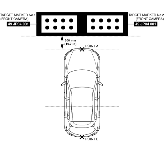
Front Camera Aiming Procedure
1.Position the SSTs at the positions shown in the figure.
am3zzw00036910
|
2.Connect the M-MDS to the DLC-2.
3.Close all the doors (front door, rear door) and the trunk lid (4SD)/liftgate (5HB).
4.Verify that the outer mirrors are unfolded.
5.Operate the electric parking brake.
6.Shift the selector lever to the P position. (ATX)
7.Shift the shift lever to the neutral position. (MTX)
8.After vehicle identification is completed, select the following from the M-MDS initial screen.
- (1)[Toolbox]
- (2)[Work Support]
- (3)[i-ACTIVSENSE]
- (4)[Static aiming]
- (5)[Static aiming for 360° View Monitor System]
9.Perform the front camera aiming procedure according to the directions on the M-MDS.
10.Verify the M-MDS display.
-
• If [Procedure completed successfully] is displayed
-
― Perform the 360° view monitor system screen display verification procedure. (See 360° View Monitor System Screen Display Verification Procedure.)
-
-
• If [Procedure not completed successfully] is displayed.
-
― Perform an inspection according to the following table for the error code procedure.― If an error code other than the error codes in the following table is displayed, verify the following and perform the front camera aiming again if there is no malfunction, as there could be a communication error between the 360° view monitor control module and the diagnostic tester.
-
1. Is the battery positive voltage for the vehicle 8 V or more?2. Is the ignition switched to ACC or ON (engine off or on)?
-
-
|
Error code |
Detection Condition |
|---|---|
|
09
|
Target marker No.1 of front camera is not detected
|
|
0A
|
Target marker No.2 of front camera is not detected
|
|
10
|
Input vehicle value exceeds specification
|
|
12
|
Because the following aiming implementation conditions are not met, the aiming is not completed.
• Vehicle stopped
• All doors (front door, rear door) and trunk lid (4SD)/liftgate (5HB) closed
• Outer mirrors unfolded
• Electric parking brake operated
• Selector lever is in P position (ATX)
• Shift lever is in neutral position (MTX)
|
|
15
|
Aiming is not possible due to malfunction in 360° view monitor control module
|
|
18
|
360° view monitor control module cannot receive front camera images
|
|
1A
|
Power supply to camera insufficient
|
Error code 09/0A/10
|
Step |
Inspection |
Action |
|
|---|---|---|---|
|
1
|
VERIFY TARGET MARKER SETTING ENVIRONMENT AND POSITION
• Verify the following.
• Display the screen of the 360° view monitor system in the center display by pressing the 360° view monitor switch.
• Is there a malfunction?
|
Yes
|
Repair the malfunctioning location and go to the next step.
|
|
No
|
Go to the next step.
|
||
|
2
|
PERFORM FRONT CAMERA AIMING
• Perform the front camera aiming.
• Was the front camera aiming procedure completed correctly?
|
Yes
|
The front camera aiming is completed. Perform the 360° view monitor system screen display verification procedure.
|
|
No
|
If error code 09/0A/10 is displayed
• Go to the next step.
If code other than error code 09/0A/10 is displayed
• Go to the procedure for the displayed error code.
|
||
|
3
|
VERIFY DTCs
• Perform the DTC inspection. (See DTC INSPECTION.)
• Is a DTC displayed?
|
Yes
|
Go to the applicable DTC inspection.
|
|
No
|
If the front camera aiming is not completed correctly after performing the front camera aiming again, replace the 360° view monitor control module.
|
||
Error code 12/15/18/1A
|
Step |
Inspection |
Action |
|
|---|---|---|---|
|
1
|
PERFORM FRONT CAMERA AIMING
• Perform the front camera aiming.
• Was the front camera aiming procedure completed correctly?
|
Yes
|
The front camera aiming is completed. Perform the 360° view monitor system screen display verification procedure.
|
|
No
|
If error code 12/15/18/1A is displayed
• Go to the next step.
If code other than error code 12/15/18/1A is displayed
• Go to the procedure for the displayed error code.
|
||
|
2
|
VERIFY DTCs
• Perform the DTC inspection. (See DTC INSPECTION.)
• Is a DTC displayed?
|
Yes
|
Go to the applicable DTC inspection.
|
|
No
|
If the front camera aiming is not completed correctly after performing the front camera aiming again, replace the 360° view monitor control module.
|
||
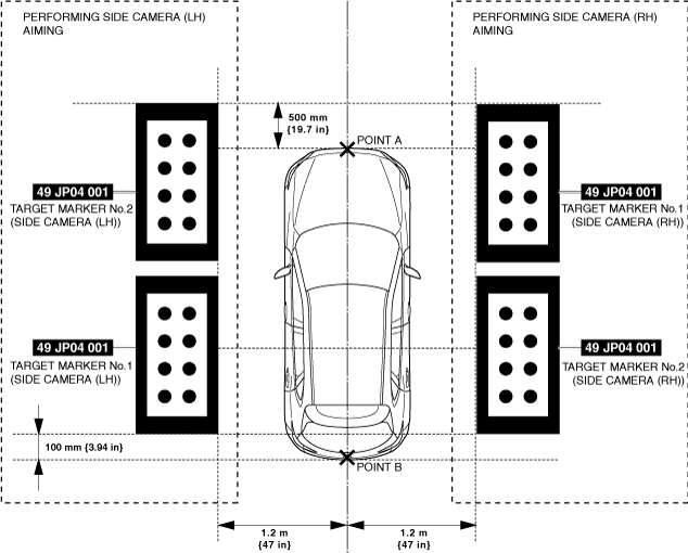
Side Camera Aiming Procedure
-
Note
-
• For the side camera aiming, 1 set(1 set/2 targets) of the SST (49 JP04 001) are required.
1.Position the SSTs at the positions shown in the figure.
am3zzw00036911
|
2.Connect the M-MDS to the DLC-2.
3.Close all the doors (front door, rear door) and the trunk lid (4SD)/liftgate (5HB).
4.Verify that the outer mirrors are unfolded.
5.Operate the electric parking brake.
6.Shift the selector lever to the P position. (ATX)
7.Shift the shift lever to the neutral position. (MTX)
8.After vehicle identification is completed, select the following from the M-MDS initial screen.
- (1)[Toolbox]
- (2)[Work Support]
- (3)[i-ACTIVSENSE]
- (4)[Static aiming]
- (5)[Static aiming for 360° View Monitor System]
9.Perform side camera aiming procedure according to the directions on the M-MDS.
10.Verify the M-MDS display.
-
• If [Procedure completed successfully] is displayed
-
― The side camera aiming is completed. Perform the 360° view monitor system screen display verification procedure. (See 360° View Monitor System Screen Display Verification Procedure.)
-
-
• If [Procedure not completed successfully] is displayed.
-
― Perform an inspection according to the following table for the error code procedure.― If an error code other than the error codes in the following table is displayed, verify the following and perform the side camera aiming again if there is no malfunction, as there could be a communication error between the 360° view monitor control module and the diagnostic tester.
-
1. Is the battery positive voltage for the vehicle 8 V or more?2. Is the ignition switched to ACC or ON (engine off or on)?
-
-
|
Error code |
Detection Condition |
|---|---|
|
06
|
Target marker No.1 of side camera (LH) is not detected
|
|
07
|
Target marker No.2 of side camera (LH) is not detected
|
|
0C
|
Target marker No.1 of side camera (RH) is not detected
|
|
0D
|
Target marker No.2 of side camera (RH) is not detected
|
|
10
|
Input vehicle value exceeds specification
|
|
12
|
Because the following aiming implementation conditions are not met, the aiming is not completed.
• Vehicle stopped
• All doors (front door, rear door) and trunk lid (4SD)/liftgate (5HB) closed
• Outer mirrors unfolded
• Electric parking brake operated
• Selector lever is in P position (ATX)
• Shift lever is in neutral position (MTX)
|
|
15
|
Aiming is not possible due to malfunction in 360° view monitor control module
|
|
17
|
360° view monitor control module cannot receive side camera (LH) images
|
|
19
|
360° view monitor control module cannot receive side camera (RH) images
|
|
1A
|
Power supply to camera insufficient
|
Error code 06/07/0C/0D/10
|
Step |
Inspection |
Action |
|
|---|---|---|---|
|
1
|
VERIFY TARGET MARKER SETTING ENVIRONMENT AND POSITION
• Verify the following.
• Display the screen of the 360° view monitor system in the center display by pressing the 360° view monitor switch.
• Is there a malfunction?
|
Yes
|
Repair the malfunctioning location and go to the next step.
|
|
No
|
Go to the next step.
|
||
|
2
|
PERFORM SIDE CAMERA AIMING
• Perform the side camera aiming.
• Was the side camera aiming procedure completed correctly?
|
Yes
|
The side camera aiming is completed. Perform the 360° view monitor system screen display verification procedure.
|
|
No
|
If error code 06/07/0C/0D/10 is displayed
• Go to the next step.
If code other than error code 06/07/0C/0D/10 is displayed
• Go to the procedure for the displayed error code.
|
||
|
3
|
VERIFY DTCs
• Perform the DTC inspection. (See DTC INSPECTION.)
• Is a DTC displayed?
|
Yes
|
Go to the applicable DTC inspection.
|
|
No
|
If the side camera aiming is not completed correctly after performing the side camera aiming again, replace the 360° view monitor control module.
|
||
Error code 12/15/17/19/1A
|
Step |
Inspection |
Action |
|
|---|---|---|---|
|
1
|
PERFORM SIDE CAMERA AIMING
• Perform the side camera aiming.
• Was the side camera aiming procedure completed correctly?
|
Yes
|
The side camera aiming is completed. Perform the 360° view monitor system screen display verification procedure.
|
|
No
|
If error code 12/15/17/19/1A is displayed
• Go to the next step.
If code other than error code 12/15/17/19/1A is displayed
• Go to the procedure for the displayed error code.
|
||
|
2
|
VERIFY DTCs
• Perform the DTC inspection. (See DTC INSPECTION.)
• Is a DTC displayed?
|
Yes
|
Go to the applicable DTC inspection.
|
|
No
|
If the side camera aiming is not completed correctly after performing the side camera aiming again, replace the 360° view monitor control module.
|
||
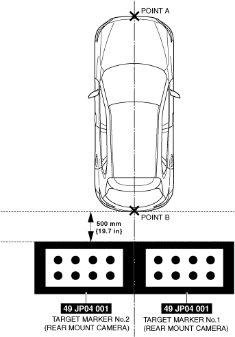
Rear Mount Camera Aiming Procedure
1.Position the SSTs at the positions shown in the figure.
am3zzw00036912
|
2.Connect the M-MDS to the DLC-2.
3.Close all the doors (front door, rear door) and the trunk lid (4SD)/liftgate (5HB).
4.Verify that the outer mirrors are unfolded.
5.Operate the electric parking brake.
6.Shift the selector lever to the P position. (ATX)
7.Shift the shift lever to the neutral position. (MTX)
8.After vehicle identification is completed, select the following from the M-MDS initial screen.
- (1)[Toolbox]
- (2)[Work Support]
- (3)[i-ACTIVSENSE]
- (4)[Static aiming]
- (5)[Static aiming for 360° View Monitor System]
9.Perform the rear mount camera aiming procedure according to the directions on the M-MDS.
10.Verify the M-MDS display.
-
• If [Procedure completed successfully] is displayed
-
― The rear mount camera aiming is completed. Perform the 360° view monitor system screen display verification procedure. (See 360° View Monitor System Screen Display Verification Procedure.)
-
-
• If [Procedure not completed successfully] is displayed.
-
― Perform an inspection according to the following table for the error code procedure.― If an error code other than the error codes in the following table is displayed, verify the following and perform the rear mount camera aiming again if there is no malfunction, as there could be a communication error between the 360° view monitor control module and the diagnostic tester.
-
1. Is the battery positive voltage for the vehicle 8 V or more?2. Is the ignition switched to ACC or ON (engine off or on)?
-
-
|
Error code |
Detection Condition |
|---|---|
|
03
|
Target marker No.1 of rear mount camera is not detected
|
|
04
|
Target marker No.2 of rear mount camera is not detected
|
|
10
|
Input vehicle value exceeds specification
|
|
12
|
Because the following aiming implementation conditions are not met, the aiming is not completed.
• Vehicle stopped
• All doors (front door, rear door) and trunk lid (4SD)/liftgate (5HB) closed
• Outer mirrors unfolded
• Electric parking brake operated
• Selector lever is in P position (ATX)
• Shift lever is in neutral position (MTX)
|
|
15
|
Aiming is not possible due to malfunction in 360° view monitor control module
|
|
16
|
360° view monitor control module cannot receive rear mount camera images
|
|
1A
|
Power supply to camera insufficient
|
Error code 03/04/10
|
Step |
Inspection |
Action |
|
|---|---|---|---|
|
1
|
VERIFY TARGET MARKER SETTING ENVIRONMENT AND POSITION
• Verify the following.
• Display the screen of the 360° view monitor system in the center display by pressing the 360° view monitor switch.
• Is there a malfunction?
|
Yes
|
Repair the malfunctioning location and go to the next step.
|
|
No
|
Go to the next step.
|
||
|
2
|
PERFORM REAR MOUNT CAMERA AIMING
• Perform the rear mount camera aiming.
• Was the rear mount camera aiming procedure completed correctly?
|
Yes
|
The rear mount camera aiming is completed. Perform the 360° view monitor system screen display verification procedure.
|
|
No
|
If error code 03/04/10 is displayed
• Go to the next step.
If code other than error code 03/04/10 is displayed
• Go to the procedure for the displayed error code.
|
||
|
3
|
VERIFY DTCs
• Perform the DTC inspection. (See DTC INSPECTION.)
• Is a DTC displayed?
|
Yes
|
Go to the applicable DTC inspection.
|
|
No
|
If the rear mount camera aiming is not completed correctly after performing the rear mount camera aiming again, replace the 360° view monitor control module.
|
||
Error code 12/15/16/1A
|
Step |
Inspection |
Action |
|
|---|---|---|---|
|
1
|
PERFORM REAR MOUNT CAMERA AIMING
• Perform the rear mount camera aiming.
• Was the rear mount camera aiming procedure completed correctly?
|
Yes
|
The rear mount camera aiming is completed. Perform the 360° view monitor system screen display verification procedure.
|
|
No
|
If error code 12/15/16/1A is displayed
• Go to the next step.
If code other than error code 12/15/16/1A is displayed
• Go to the procedure for the displayed error code.
|
||
|
2
|
VERIFY DTCs
• Perform the DTC inspection. (See DTC INSPECTION.)
• Is a DTC displayed?
|
Yes
|
Go to the applicable DTC inspection.
|
|
No
|
If the rear mount camera aiming is not completed correctly after performing the rear mount camera aiming again, replace the 360° view monitor control module.
|
||