BODY CONTROL MODULE (BCM) REMOVAL/INSTALLATION
BODY CONTROL MODULE (BCM) REMOVAL/INSTALLATION
SM2336729
id094000003800
-
Caution
-
• When replacing the body control module (BCM), perform the configuration to assure that the system operates correctly. (See CONFIGURATION.)
1.When replacing the body control module (BCM), perform the following procedure.
- (1)Perform manual configuration using the following procedure.
-
- 1)Verify the following setting values with the customer. (See PERSONALIZATION FEATURES [(US)].) (See VEHICLE STATUS MONITOR SETTING.)
-
-
• Personalization features
-
• Vehicle status monitor
-
- 2)Connect the M-MDS to the DLC-2.
- 3)Switch the ignition ON (engine off or on).
- 4)Perform vehicle identification.
- 5)Select [Configuration] using the M-MDS.
- 6)Select [BCM].
- 7)Perform manual configuration following the instructions on the screen.
- (2)Leave the front doors on both sides and the trunk lid (4SD) or liftgate (5HB) open until the synchronization between the following units and the body control module (BCM) is complete.
-
-
• Electrical Supply Unit (ESU)
-
• Door-electrical supply unit
-
- (3)Turn the wiper and washer switch off.
2.Disconnect the negative battery terminal. (See NEGATIVE BATTERY TERMINAL DISCONNECTION/CONNECTION [(US)].)
3.Remove the front scuff plate (LH). (See FRONT SCUFF PLATE REMOVAL/INSTALLATION.)
4.Remove the front side trim (LH). (See FRONT SIDE TRIM REMOVAL/INSTALLATION.)
5.Disconnect the connectors.
am3zzw00028093
|
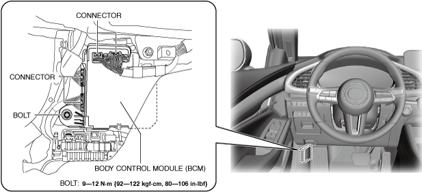
6.Remove the bolt.
7.Move the body control module (BCM) in the direction of the arrow shown in the figure and detach the body control module (BCM) hook from the body control module (BCM) bracket.
am3zzw00028094
|
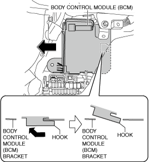
8.Remove the body control module (BCM).
9.Install in the reverse order of removal.
10.If the body control module (BCM) is replaced, perform the following procedure:
- (1)Switch the ignition ON (engine off or on) and wait for 1 s or more, then synchronize the following units with the body control module (BCM).
-
-
• Electrical Supply Unit (ESU)
-
• Door-electrical supply unit
-
- (2)Perform manual configuration following the instructions on the M-MDS screen.
-
-
Note
-
• If manual configuration is performed using the As-Built data, the following information is reset to the initial values (condition when shipped from factory).
-
― Odometer/tripmeter― Personalization features― Vehicle status monitor
-
-
- (3)Perform the immobilizer system-related part programming using the M-MDS. (See IMMOBILIZER SYSTEM-RELATED PARTS PROGRAMMING [(US)].)
- (4)Clear the position memory system memory using the M-MDS. (With position memory system) (See POSITION MEMORY SYSTEM MEMORY CLEARING.)
- (5)Perform the VCM initial setting using the M-MDS. (See VCM INITIAL SETTING.)
- (6)Perform the DTC inspection. (See DTC INSPECTION.)
-
-
• If a DTC is displayed, clear it. (See CLEARING DTC.)
-
- (7)If manual configuration is performed using the As-Built data, perform the personalization features setting and vehicle status monitor setting. (See PERSONALIZATION FEATURES [(US)].) (See VEHICLE STATUS MONITOR SETTING.)